The LeadTurbo team offers global reverse-engineering support for turbocharger parts remanufacturers, providing high-quality, compatible replacement components you can rely on.
LeadTurbo: Our Reverse-Engineering Process for High-Quality Turbocharger Parts.
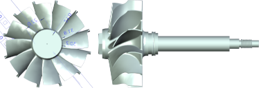
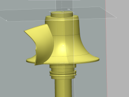
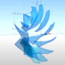
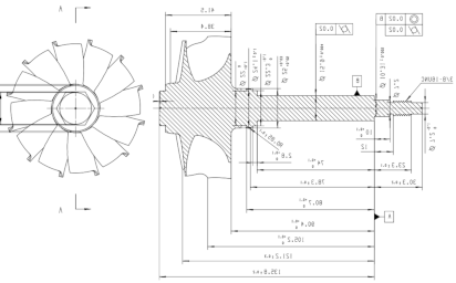
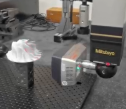 Under the extraordinary precision of our Mitutoyo laser measurement system, we generate massive point clouds—on the scale of hundreds of millions of data points—achieving measurement error as low as 0.01 mm or even finer. These finely detailed datasets empower us to trace every nuanced contour and curvature with near-perfect accuracy. From this rich foundation, we reconstruct ultra-faithful 3D meshes that mirror the real object in uncanny detail, delivering models so precise they leave no room for speculation.
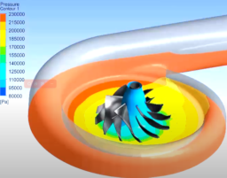
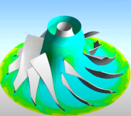
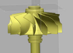
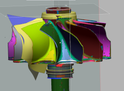
 Backed by high-fidelity FEA simulations, our team probes every possible scenario—from extreme stress and wear to tight-tolerance fits and thermal cycling—so you don’t have to. We catch problems long before prototyping, shorten development cycles, lower production costs, and ensure products hit the market with proven reliability. The final CAD drawings are not just accurate; they’re ready for smooth tooling, assembly, and certification.
The outcome is clear: faster time-to-market, lower costs, and turbocharger parts you can trust.
How does LeadTurbo Guarantees Product Quality?
Prevent recurrence: Don’t generate the same problem—aim for root-cause correction and learning.
Mistake proofing & risk prevention: Implement DFMEA/PFMEA and proactive controls.
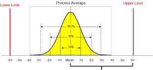
 Six Sigma is the cornerstone of our quality management system and reflects LeadTurbo’s unwavering commitment to excellence. We apply the DMAIC cycle across our operations to drive continuous improvement, rigorously refine every process, and ensure that customer satisfaction is the outcome—not merely a goal.
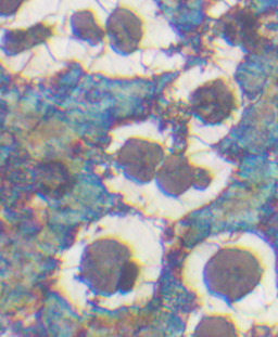 At the heart of our quality assurance is a laboratory that performs comprehensive evaluations of raw materials. We verify chemical composition, Rockwell hardness, yield strength, elongation, tensile strength, and conduct metallographic (microstructural) analysis to confirm material integrity and eliminate any substandard supplies.
Our chemical analysis capability is anchored by the Olympus Vanta VCR Series Handheld X-Ray Fluorescence (XRF) Analyzer. Every batch of raw material is screened with this advanced instrument, and all results are recorded and retained to ensure full traceability.
 Every turbine-shaft component and complete assembly we supply includes a turbine-head chemical composition certificate derived from Vanta VCR testing. This documentation provides clear, auditable proof that the INCO 713C (K418) material we use meets specified requirements and industry expectations.
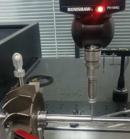
Quality control continues through production: 100% of critical machining dimensions are inspected using program-driven Mitutoyo Coordinate Measuring Machines (CMMs). Automated measurement routines ensure objective, impartial results and complete data traceability—measurement records are securely stored and shared with customers to support transparency and continuous improvement.
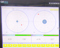
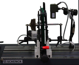 Dynamic balance is validated on Schenck balancing systems that deliver SI-traceable, highly accurate results. Every turbine shaft we ship is accompanied by a balancing report certifying residual unbalance well below 20 mg—minimizing customers’ post-assembly balancing effort and accelerating time to service.
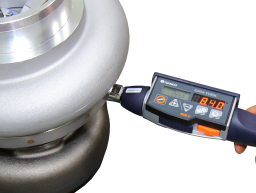
During final assembly, we adhere strictly to documented SOPs and use calibrated torque wrenches on every fastener to guarantee consistent, specification-compliant installation.
Together, these systems and practices ensure that every LeadTurbo product delivers dependable performance, traceable quality, and the confidence our customers expect.
LeadTurbo Exhaust Gas Turbocharging Solutions: Engineering Excellence
LeadTurbo is at the forefront of turbocharger innovation, delivering exhaust gas turbocharging solutions engineered for maximum performance and durability. Our systems harness otherwise-wasted exhaust energy to dramatically boost engine power and efficiency. By integrating advanced aerodynamics, high-grade materials, and intelligent controls, LeadTurbo turbochargers enable engines to achieve higher torque and responsiveness without sacrificing fuel economy or reliability. The following sections (Structural Composition, Thermodynamics, Control Strategies) highlight the key design elements that set LeadTurbo solutions apart in innovation and reliability.
Structural Composition
LeadTurbo turbochargers are built on a foundation of robust architecture and precision engineering. Every component is optimized for strength, light weight, and longevity. Key features include:
- Advanced Wheel Materials: LeadTurbo’s compressor wheels are crafted from high-strength aluminum alloys (with optional titanium or stainless-steel variants), while our turbine wheels use nickel-based superalloys. These cutting-edge materials offer the ideal balance of weight, strength, and heat resistance for extreme exhaust temperatures
- Precision Bearing Assembly: The rotating shaft assembly (CHRA) features a thrust bearing plus two fully-floating journal bearings. This bearing system precisely controls radial and axial shaft motion while minimizing friction losses. The result is smoother high-speed rotation, faster spool-up, and extended bearing life under heavy duty cycles.
- High-Strength Housings: LeadTurbo turbine housings are cast from premium high-grade alloys or iron with heat-resistant coatings. The center housing is typically gray cast iron (or specialty alloy) with integrated oil and coolant passages for efficient thermal management. These features ensure that oil temperatures stay in safe limits and parts withstand the most extreme operating conditions.
- High-Precision Rotor Assembly: Each LeadTurbo rotor is meticulously balanced to aerospace tolerances. Lightweight, high-velocity shafts and blades reduce inertia and vibration. This dynamic balancing (and tight manufacturing tolerances) enhances reliability and minimizes noise, even at operational speeds exceeding 150,000 rpm.
Through these structural innovations—proprietary wheel geometries, advanced alloys, and precision bearing and housing designs—LeadTurbo turbochargers deliver industry-leading durability and consistency.
Thermodynamics and Performance
LeadTurbo’s design harnesses thermodynamic principles to maximize engine performance. Our turbochargers extract exhaust energy to compress intake air, significantly increasing engine torque and power. As LeadTurbo emphasizes, turbocharger performance “influences all important engine parameters, such as fuel economy, power, and emissions”. By optimizing each stage for efficiency, LeadTurbo systems improve all three of these critical metrics. Highlights include:
- Optimized Compressor Aerodynamics: LeadTurbo compressors use advanced impeller blade profiles (designed via state-of-the-art CFD analysis) to achieve high pressure ratios with minimal flow losses. This yields a wide efficiency island on the compressor map and high mass airflow across the operating range.
- Efficient Turbine Stage: Our turbine nozzles and wheels are engineered to extract maximum work from hot exhaust gases. We offer options like dual-entry turbines and electronic variable-geometry exhaust guides to maintain optimal back-pressure across varying speeds. The result is higher exhaust enthalpy extraction and a flatter performance curve, giving engines strong mid-range torque and peak power without spikes in exhaust backpressure.
- Variable-Geometry Technology: LeadTurbo’s VGT turbos employ movable vanes in the turbine inlet, eliminating the throttling losses of fixed-geometry wastegates. This technology enables significantly higher air–fuel ratios and peak torque at low engine speeds, along with improved acceleration across the RPM band. In practice, this means engines spool up faster and deliver consistent power whether crawling in traffic or sprinting up a hill.
- Rapid Dynamic Response: Thanks to low-inertia components and optimized rotor aerodynamics, LeadTurbo turbos reach operating speed very quickly. The combination of balanced rotors and tight bearing tolerances produces minimal lag, so boost builds almost instantaneously as throttle opens.
These thermodynamic enhancements translate directly into real-world benefits: engines equipped with LeadTurbo turbochargers show higher horsepower and torque curves, improved fuel efficiency, and cleaner combustion under diverse conditions. In short, LeadTurbo units expand the usable performance envelope of the engine, delivering more work from the same fuel input.
Control Strategies
Intelligent control is critical to harnessing turbocharger potential, and LeadTurbo integrates advanced strategies to manage boost safely and effectively. Our engineering team designs each system with the following features:
- Precision Wastegate Actuation: All LeadTurbo turbos come with carefully sized wastegates (internal or optional external) to regulate boost pressure. High-speed pneumatic or electronic actuators, coordinated by the engine control unit (ECU), modulate exhaust bypass flow. This ensures consistent, chatter-free boost control and prevents over-boost conditions.
- Electronically-Controlled Vanes (VGT models): For models equipped with variable-geometry turbines, fast-response actuators adjust vane angles in real time. This active control maximizes low-end torque and engine braking capability without sacrificing high-end efficiency. The system responds within milliseconds to changes in throttle and load, offering smooth torque delivery across the entire RPM range.
- Blow-Off Valves and Surge Protection: LeadTurbo systems can include high-flow blow-off valves to protect against compressor surge during sudden throttle closures. By venting excess charge pressure quickly, the BOV prevents spikes that could damage the compressor wheel or cause instability. This contributes to smoother throttle transitions and component longevity.
- ECU Integration and Closed-Loop Control: Each turbocharger is supplied with detailed calibration maps and integrated sensor feedback. LeadTurbo works with customers to program boost targets, limiter logic, and transient response curves into the engine ECU. Real-time pressure and temperature sensors enable closed-loop boost control, ensuring the turbocharger operates safely within its design limits under all conditions.
Together, these control strategies yield a turbocharging system that is not only powerful but also highly predictable and safe. LeadTurbo turbochargers are engineered by LeadTurbo experts to meet stringent durability standards: each unit undergoes exhaustive testing on engine dynos and flow benches before delivery. This commitment to control precision and quality means end-users experience reliable, consistent performance without compromise.
LeadTurbo turbocharging solutions are engineered for innovation, reliability, and excellence, combining premium materials, advanced design, and rigorous testing to deliver unmatched performance, efficiency, and durability—all backed by our hallmark of precision manufacturing.
A Preliminary Understanding of Exhaust Gas Turbochargers — LeadTurbo
Abstract
This technical report—authored by engineers—offers a systematic derivation of exhaust gas turbocharger operating principles and energy flows. It presents key equations, design-matching considerations, control strategies, and typical failure-diagnosis procedures. The engineering team has also included representative numerical examples based on typical engine operating conditions, together with result tables to aid in performance estimation and preliminary component matching
System Description and Components
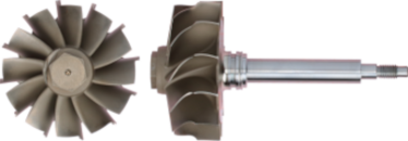
Figure: Cross-sectional schematic of a typical exhaust-gas turbocharger. The turbine (right) extracts energy from engine exhaust, driving the coaxial compressor (left) to boost intake air pressure.
A typical turbocharger consists of two main rotors on a single shaft: the turbine (driven by exhaust gas) and the compressor (driving intake air). Exhaust gas enters the turbine housing and impinges on turbine blades; as the turbine wheel spins, it drives the compressor wheel in the compressor housing via a forged shaft. The center housing (bearing housing) between them supports this shaft on journal and thrust bearings, and provides oil (and often coolant) flow for lubrication and cooling. Seals at each end prevent exhaust or intake air from leaking into the bearing chamber. An intercooler is often placed downstream of the compressor to remove heat from the compressed air, improving density. Additional hardware can include a wastegate or bypass valve (to regulate turbine flow) and, in VGT turbos, a variable-geometry vane mechanism within the turbine inlet (see below).
Modern turbos may use fixed-geometry housings, wastegates, or variable-geometry turbines depending on application. Light alloys or high-temperature steels are used to withstand exhaust temperatures (often >800°C) and high rotational speeds (up to hundreds of thousands of RPM). The rotating group (Shaft Wheel Assembly) spins in a floating bearing system to minimize friction losses. In summary, “a turbocharger consists of a single-stage radial-flow compressor… driven by a single-stage radial-flow exhaust turbine.” The turbine extracts exhaust gas kinetic/thermal energy to produce shaft power for the compressor.
Thermodynamic and Energy Analysis
From a thermodynamic viewpoint, the turbocharger mediates the energy transfer between exhaust and intake air. In steady-state, the power extracted by the turbine (from exhaust gas enthalpy drop) must equal the power required by the compressor (to raise intake air pressure) plus mechanical losses (bearing friction, seal leakages, etc.). In an idealized energy balance (neglecting heat loss to structure), the turbine’s extracted power is:
where is the exhaust mass flow and its specific heat. The actual turbine shaft power delivered, , is lower by the turbine’s isentropic efficiency :
Similarly, the compressor draws power
,
where is the intake air mass flow, and are the compressor inlet and actual outlet temperatures, and is air’s specific heat. For an ideal isentropic compression to a pressure ratio , the outlet temperature satisfies
where . The compressor’s isentropic efficiency relates this ideal temperature rise to the real one by
so that
Thus the actual compressor work can be computed. (These relations assume constant ; for high accuracy, one would use enthalpy from real-gas tables and include intercooling or heat transfer if present.)
Turbine–Compressor Matching
At steady state, the turbine must supply the compressor’s demand: . In practice one solves Equivalently, given the desired pressure ratio and flow, one can iterate the above formulas to find the required or check if the turbine can meet the compressor load. Mechanical losses (bearings/seals) are often accounted for by a margin or added torque to .
The isentropic efficiency terms encapsulate internal irreversibilities: values might be 60–80% for compressors and 65–75% for turbines in typical automotive turbos. These definitions mean the actual temperature (or enthalpy) change exceeds the ideal change by 1/η.
Performance Metrics and Maps
Key turbocharger performance parameters include pressure ratio (PR), mass flow , speed (shaft RPM), and efficiency. PR is defined as across the compressor. Typical compressor maps are plotted with pressure ratio vertical vs. mass flow horizontal; each iso-speed line shows the performance at fixed shaft speed. Concentric “efficiency islands” (contours) illustrate compressor adiabatic efficiency at each operating point. The left boundary is the surge line (minimum stable flow), and the right boundary is the choke line (maximum flow before the compressor flow becomes sonic or very inefficient). As speed increases, the map curves move up and right: higher speeds allow higher PR or flow.
Figure 1 (example, not included) shows a schematic compressor map. When matching a turbo to an engine, the engine’s required airflow and boost at each operating point can be plotted on this map to ensure it lies within the turbo’s acceptable region. Performance goals (peak power, torque shape) dictate choosing a compressor/turbine pair whose map envelop includes the needed flow/PR range.
Common derived metrics also include maximum allowable RPM (turbo redline), and turbocharger inertia (affecting transient response). Turbo lag time and boost response depend on how quickly the turbine can accelerate, which is influenced by rotor inertia and exhaust energy. In practice, engineers use normalized (non-dimensional) flow and speed parameters when matching turbos, but the underlying principle is as above
Control Strategies and Dynamic Response
Modern turbochargers incorporate controls to manage boost:
- Wastegate (bypass valve): A simple pneumatic or electronic valve that opens to allow exhaust to bypass the turbine wheel when boost exceeds a setpoint. By venting some flow, the wastegate limits turbine RPM and prevents overboost. A closed wastegate effectively makes the turbine housing “smaller” (a low A/R ratio) for rapid spool-up at low engine speed. At high load, opening the wastegate increases effective flow area and prevents excessive boost. Overall, wastegate control allows a single fixed-geometry turbo to operate safely over a wide range
- Variable-Geometry Turbine (VGT/VNT): Instead of a wastegate, VGT turbos adjust the turbine inlet geometry with movable vanes or nozzles. By closing vanes, the turbine sees a smaller area (high gas velocity) at low engine speed, improving spool-up; by opening vanes at high speed, the turbine back-pressure is reduced. This self-adjusting flow control maximizes boost across the full RPM range and greatly reduces lag. VGT is especially common on diesel engines.
- Twin-Scroll and Twin-Turbo Systems: In a twin-scroll turbocharger, the turbine housing has two separate inlets that keep engine exhaust pulses from different cylinders separated, improving energy extraction and low-end response. Twin-scroll (or even two sequential turbos of different sizes) can give faster boost and higher peak power. These setups essentially provide the fast spool of a small turbo at low RPM and the high-flow capacity of a larger turbo at high RPM.
Turbocharger dynamic response (lag) depends on rotor inertia, exhaust flow dynamics, and control strategy. Large-mass wheels take more exhaust energy and time to accelerate; high exhaust mass flow and enthalpy accelerate spool-up . Engine exhaust pulse shaping (e.g. tuned manifolds) can also affect response. In general, reducing rotor inertia (lightweight wheels), using turbine aids (VGT, twin-scroll), or improving exhaust flow (exhaust headers, short piping) will reduce lag. For example, BR-Turbo notes that “size and design [are] significant components of lag — big turbos produce much power but have higher inertia” , and that “Variable Geometry Turbos…regulat[e] the angle of the vane… allowing lag reduction.” . Thus, matched with engine controls, these strategies yield quicker boost response.
Common Fault Modes and Diagnostic Checks
Turbochargers are generally robust, but various faults can occur:
- Bearing/shaft failure: Oil starvation or contamination can cause bearing wear. Symptoms include unusual high-frequency noise or vibration, and excessive axial or radial shaft play. Bearings often wear quietly until sudden failure; as Garrett notes, oil-borne particles (e.g. carbon) can abrade bearing surfaces, increasing clearance and causing oil to leak past seals. Diagnosis: check oil pressure and quality, perform end-play (axial) and radial-play measurements, and inspect bearing housing for wear.
- Compressor or turbine blade damage (FOD): Foreign Object Damage or fatigue can crack or chip blades. Look for nicks, dents, or missing pieces on the wheels. A bent or damaged blade often causes strong vibrations and can rapidly worsen. Inspection is done visually (borescope or after removal).
- Seal or oil leakage: Excessive oil in the intake or exhaust can indicate worn shaft seals or high crankcase/exhaust pressure. Oil may enter the compressor housing or slipstream. Check crankcase ventilation, measure exhaust back-pressure, and inspect seal integrity. (Notes: that bearing wear often leads to oil bypassing the turbine end seal, causing smokey exhaust.)
- Boost loss or instability: If manifold boost is lower than expected, common causes are intake/exhaust leaks, intercooler rupture, stuck/open wastegate, or control actuator failure. Diagnostic methods include boost pressure decay/leak tests, checking actuator function, and inspecting intercooler and piping for leaks or damage.
Diagnostic checklist: Perform a boost leak-down test to find air leaks, monitor exhaust and inlet temperatures (anomalies can indicate inefficiency or blockage), use vibration or acoustic analysis for bearing health, and sample engine oil for wear particles. Measuring turbo inlet and outlet pressures and temperatures, and using endoscope inspections, help pinpoint faults early.
Design and Matching Guidelines
In engineering practice, turbocharger sizing and integration follow these principles:
- Match to engine operating range: Select compressor and turbine sizes so that at the target operating points (power/torque curve) the flow and pressure requirements lie within the efficient region of the turbo maps. This is done by calculating engine air flow and exhaust flow/temperature at desired RPM/torque, then choosing a turbo whose map covers those points.
- Balance responsiveness vs. durability: Lower-inertia wheels (e.g. titanium or ceramic) spool faster but may have lower mechanical strength. High peak-power turbos often have beefier turbines or ball-bearing designs to tolerate extreme heat and RPM.
- Bearing and cooling design: Ensure adequate oil flow and, if necessary, water-cooling for the center housing on high-heat engines. Many high-performance turbos use journal bearings with oil jets, or ball bearings with oil-air hybrid designs. Prevent oil coking by advising proper warm-up/cool-down procedures.
- Intercooler and thermal management: Use an intercooler to reduce charge-air temperature, which increases air density and reduces knock risk. Good intercooling can allow higher boost or improve torque. Also consider insulating or cooling exhaust components to maintain turbine efficiency and protect nearby structures.
- Control integration: For wastegated or VGT turbos, the actuator and boost control must be tuned to the engine ECU. The wastegate spring (or VGT schedule) is chosen so that target boost is reached without overshoot. Ensure actuator response (and safety fail-safes) are designed to handle transient spikes.
In all cases, practical matching uses manufacturer compressor and turbine maps (provided by suppliers) rather than constant- assumptions. Simulation tools or look-up of manufacturer data allow point-by-point matching of non-dimensional flow and speed.
Example Calculation
Assumed conditions (steady-state engine case): intake compressor pressure ratio , ; efficiencies , .
- Compressor ideal outlet temperature:
- Compressor actual outlet temperature: Using , solve :
- Compressor power required:
- Turbine ideal power needed: To drive the compressor, turbine shaft power must equal (ignoring losses). Thus and
- Turbine ideal outlet temperature: Assume ideal expansion: Solving:
Results: Under these assumptions, the turbine extracts about 27.3 kW of ideal power to supply the 19.1 kW compressor load. The estimated compressor outlet temperature is 376.2 K, and the turbine outlet (ideal) is 758.6 K. These values neglect mechanical losses and use constant . In practice, a detailed design would use enthalpy tables and include friction losses, but this example provides an engineering-level estimate.
Conclusions and Further Work
This report has outlined the key principles and formulas for exhaust-gas turbocharger operation, suitable for initial engineering calculations and conceptual matching. We derived the power balance between turbine and compressor, and showed how isentropic relations and efficiencies determine temperatures and work. Control methods (wastegate, VGT) and performance mappings were summarized, and typical fault checks and design guidelines were presented.
For detailed design and validation, further steps are recommended: use actual manufacturer compressor and turbine maps to match flow-speed points precisely, employ real-gas enthalpy (via charts or software) rather than constant , and include mechanical loss estimates. Dynamic behavior should be assessed with transient modeling (including rotor inertia, exhaust pressure pulsations, and actuator response). Additionally, experimental calibration and durability testing under realistic cycles will ensure the chosen turbo performs as intended.
Should you require more details, please reach out to LeadTurbo.