Reverse engineering from the real sample
Point-cloud capture, virtual validation and CAM integration shorten the path from worn hardware to production-ready parts.
LeadTurbo supports rebuilders with reverse engineering, quality assurance and component-level turbocharger knowledge so the sourcing conversation moves from sample to dependable production part without guesswork.
 Reverse engineering to production
Point-cloud capture, virtual validation and CAM integration shorten the path from worn hardware to production-ready parts.
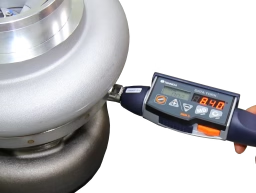
Laboratory checks, CMM inspection and balancing reports keep material, dimensions and assembly quality visible through the process.
LeadTurbo works at component level and system level, from housings and wheels to matching, response and durability questions.
Measurement, simulation and manufacturing preparation each solve a different risk. Put together, they reduce ambiguity before the part ever reaches the machine or the rebuilder's bench.
The process starts from real hardware, not assumptions, so the digital model reflects the part you actually need to reproduce.
Loads, fit, heat and failure risks are checked before the design is released for machining or tooling decisions.
Toolpaths, fixtures and CNC programs are prepared so the part can move into repeatable production with fewer setup loops.
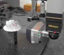
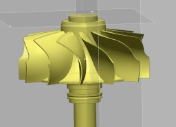
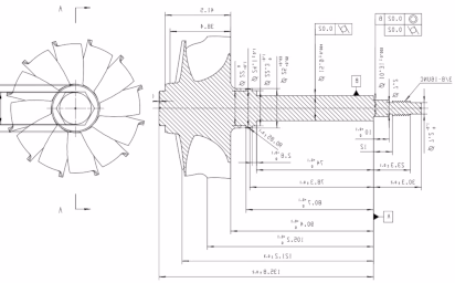
LeadTurbo begins by capturing the actual part geometry at very fine resolution. The point cloud becomes the base reference for reconstructing surfaces, edges and transitional shapes that usually get lost in manual measurement alone.
That means the CAD work starts from real geometry with measured evidence behind it, not estimation from a few visible dimensions.
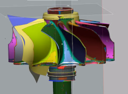
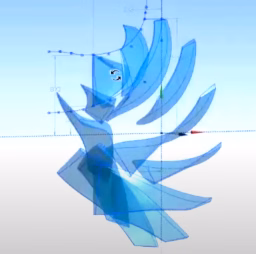
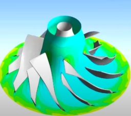
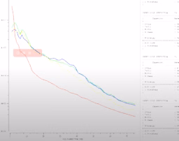
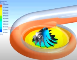
The digital model is checked against stress, fit, thermal load and service conditions before release. That helps expose weak geometry, poor stack-up assumptions or durability risks before time gets spent on tooling and trial manufacturing.
The goal is practical: shorten iteration cycles, lower correction cost and hand over a drawing set that is already closer to production reality.
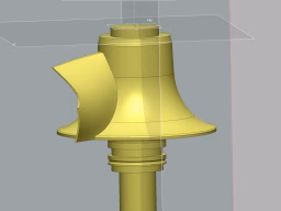
When the geometry is validated, CAM takes it into toolpaths, collision checks, fixture logic and CNC-ready programs. That closes the gap between drawing approval and repeatable machining.
Revision control and machine-oriented outputs help reduce setup iteration and keep the released process aligned with the validated model.
LeadTurbo's quality work is not one checkpoint at the end. It is a chain of controls that starts with raw material verification and continues through dimensional inspection, assembly discipline and balancing.
Corrective action is built around root cause, preventive controls and process learning rather than one-off fixes.
Chemical composition, hardness and metallographic checks help keep low-grade inputs out of the process.
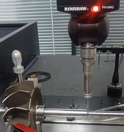
Critical dimensions are verified with repeatable CMM routines and the records remain available for traceability.
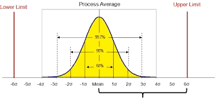
Turbine shafts and assemblies are balanced with reportable results so the final build starts from a stable rotating group.

LeadTurbo uses Six Sigma thinking to drive corrective action toward root cause, not symptom management. That matters because recurring quality drift is usually a process issue, not just an operator issue.
DFMEA, PFMEA and preventive controls are used to reduce repeat failures and make process learning stick.

Raw material is checked for chemical composition, hardness, tensile properties and metallographic condition before it becomes an accepted input to production.
XRF analysis and retained records support traceability, especially where turbine-shaft material compliance matters to the rebuilder.
Program-driven CMM inspection removes a large amount of subjective variation from dimensional verification and makes the records easier to store, compare and share.
For the customer, that means objective dimensional evidence rather than a general statement that the part was checked.

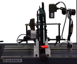
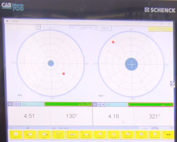
Dynamic balance is verified with documented results so turbine shafts and assemblies arrive with a controlled starting point for final build quality.
Combined with controlled assembly torque and SOP discipline, that reduces post-assembly correction work and protects service reliability.
The company is not limited to isolated spare parts. The engineering context spans rotating hardware, housing design, airflow behavior, control strategy and practical matching decisions.
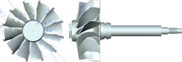
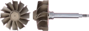
Rotor group, housings and bearing stack decisions that shape durability and fit.
Compressor wheels in high-strength aluminum, with turbine wheels based on heat-resistant nickel alloys where the duty cycle requires it.
Thrust and journal bearing control is built around stable shaft support and reduced friction across the operating range.
Turbine and center housing design must handle heat, sealing and fluid passages without introducing avoidable instability.
Tight manufacturing and balance control help keep noise, vibration and service risk down at very high shaft speed.
Compressor, turbine and vane decisions affect response, efficiency and the usable map range.
Blade profiles and flow path decisions target pressure ratio, stability and usable efficiency across the map.
Turbine stage design determines how effectively exhaust energy becomes shaft work for the compressor.
Vane control helps expand the effective response window, especially where low-speed torque matters.
Wastegate, actuator and surge-control decisions matter as much as the hardware itself.
Boost control hardware has to match the intended flow range without creating unstable or delayed response.
Sensor feedback and calibration logic help keep the turbo inside safe operating limits under changing engine demand.
Fast vane actuation improves low-end response and broadens the operating window when the system is matched correctly.
Blow-off and related control measures help protect the compressor when the engine demand changes abruptly.
This section condenses the longer engineering content into a cleaner reference format. It covers the system architecture, power balance, map interpretation, control logic, failure modes and a simple steady-state calculation example.
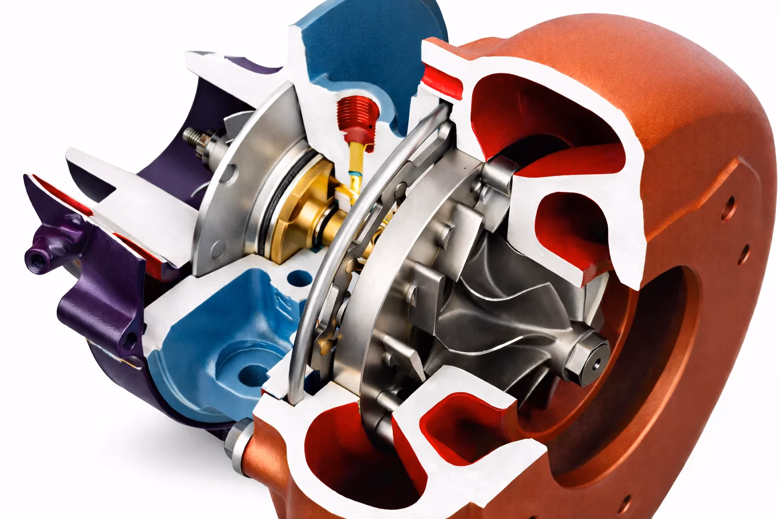
A turbocharger combines a turbine, compressor and shared shaft so exhaust energy can raise intake pressure. Around that core, the bearing system, housings, seals, cooling passages and control hardware determine how stable and durable the system is in service.
In practice, the component-level choices and the control strategy must be read together. A strong wheel or housing alone does not guarantee a good turbo system.
At steady state, the turbine has to provide at least the power demanded by the compressor plus mechanical losses. That makes matching a power-balance problem before it becomes a packaging problem.
P_t = m_ex * cp_ex * (T_in - T_out)
P_c = m_air * cp_air * (T2 - T1)
P_t * eta_t >= P_c + P_loss
These quick relations are useful for concept work. Detailed matching still needs actual maps, real-gas enthalpy and measured operating points.
Pressure ratio, mass flow, shaft speed and efficiency define whether a turbo operates in a useful region of the map. The control hardware decides how often the engine actually stays there.
Good control strategy does not rescue a badly matched turbo, but a good match can still be degraded by poor control decisions.
Usually tied to oil starvation, contamination or clearance loss. Check pressure, cleanliness and shaft play before assuming the hardware itself is the original cause.
Foreign-object damage and fatigue both show up in blade condition. Borescope inspection and path cleaning matter before another unit goes back into service.
Oil in the intake or exhaust can point to seal distress, but also to pressure imbalance, ventilation issues or bearing wear elsewhere in the system.
Low boost often sits outside the turbo itself: leaks, actuator faults, intercooler damage or exhaust-side restriction can all look like a hardware problem first.
The practical rule is simple: map-based matching and validation data should drive the final decision, not intuition alone.
m_ex = 0.60 kg/s
m_air = 0.25 kg/s
PR = 1.8
eta_c = 0.72 | eta_t = 0.70
T2s = 300 * 1.8^0.286 ~= 354.9 K
T2 = 300 + (354.9 - 300) / 0.72 ~= 376.2 K
P_c = 0.25 * 1005 * (376.2 - 300) ~= 19.1 kW
P_t,ideal = 19.1 / 0.70 ~= 27.3 kW
Whether the request starts from a worn core, a dimensional problem or a new market requirement, the next step is the same: get the references in front of the engineering team and narrow the risk early.