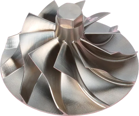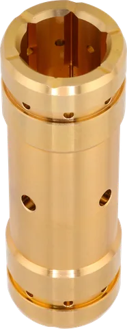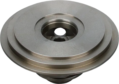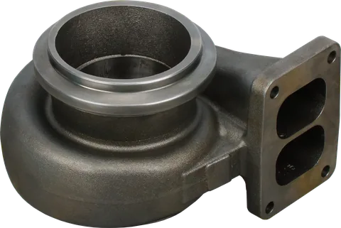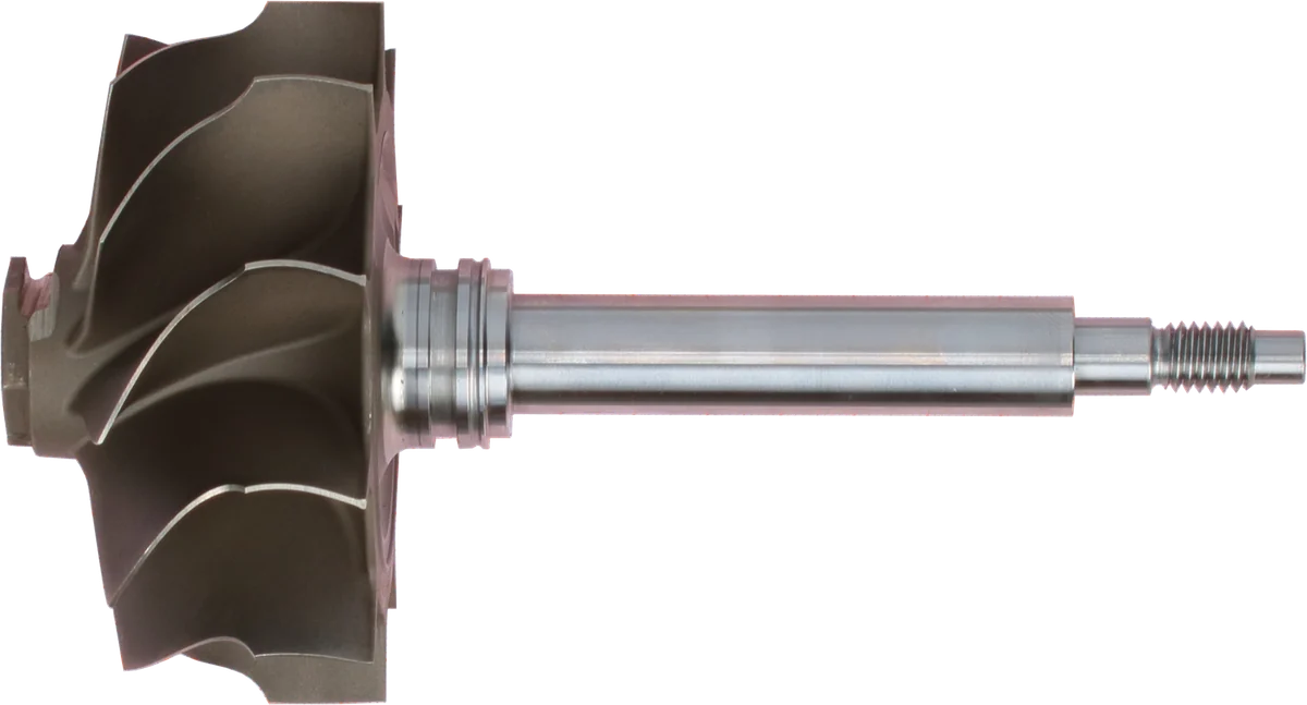
For a replacement job, deciding which turbocharger turbine wheel size to order starts with the complete turbo part number and application specification. A wheel advertised as “larger” or “high flow” may require a different housing profile or shaft assembly. For an upgrade, establish where the engine needs useful torque and how long it stays under load. Those details matter more than a diameter taken from an unrelated turbocharger.
If the original application remains unchanged, matching the specified turbine geometry is usually the most dependable rebuild route. An upgrade needs evidence from the engine’s working range.
What does turbine wheel trim actually describe?
On a conventional radial-inflow turbine, exhaust enters around the wheel’s larger outside diameter and exits through the smaller diameter facing the exhaust outlet. The entry diameter is the inducer; the exit diameter is the exducer. Parts listings may reverse the displayed order, so confirm which number is which.
For this common wheel layout, here is how to calculate turbocharger turbine trim: divide exducer diameter by inducer diameter, square the result, and multiply by 100.
| Measurement | Useful meaning | Limitation |
|---|---|---|
| Inducer diameter | Larger diameter at exhaust entry | Does not establish the exit passage dimensions |
| Exducer diameter | Outlet blade-tip diameter | Does not establish usable flow area without the hub and blade geometry |
| Trim | Relative size of the exducer | Does not provide physical size, a flow rating, or a fitment approval |
Trim describes proportion, not millimeters or measured flow. An advertised “60 mm turbine” is incomplete identification unless the seller states the measurement location. Request both diameters and the relevant part number.
Why the exhaust side needs more information
A turbine converts part of the exhaust’s available energy into shaft work as gas expands and changes direction through its blades. The housing directs gas toward the wheel; the blade passages turn the flow, producing torque. At steady speed, turbine power must supply the compressor’s demand and mechanical losses. During acceleration, additional power must accelerate the rotating assembly.
Compared with the relatively steady compressor inlet, the turbine receives hot gas pulses shaped by combustion. Exhaust temperature, fuel delivery, valve timing, manifold layout, and downstream restriction all affect its operating conditions. A working diesel can move from lightly fueled operation to heavy load without a large engine-speed change.
Turbine flow capacity therefore needs stated test conditions and a defined housing. A bare wheel diameter cannot tell you how much exhaust a stage will pass efficiently. Compressor requirements establish the air target, but the turbine must deliver sufficient power throughout the engine’s actual load range.
A downstream blockage also changes the pressure available across the turbine. Consequently, the same wheel can behave differently when the exhaust system’s condition changes.
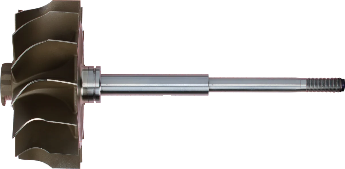
Turbine wheel: exhaust energy drives the shaft.
Shaft surface: inspect wear and scoring before reuse.
Shaft end: connects to the compressor-side rotating parts.
Product photograph from 2026. Numbers identify the features explained below.
How wheel diameter and housing work together
In comparable designs, increasing turbine wheel size can provide more passage area and room for higher exhaust flow. It can also increase rotational inertia and change the torque required for useful acceleration. Blade angles, blade count, hub size, and efficiency prevent a simple “larger equals slower” rule.
At a fixed inducer diameter, a larger exducer often increases potential flow capacity within a related wheel family. That expectation still needs a suitable housing and supporting data; trim alone cannot quantify the improvement.
Housing A/R changes how the housing feeds the wheel. Within one compatible family, a smaller A/R generally favors earlier response but may raise exhaust pressure under heavy load. A larger version generally provides more flow capacity, with a possible response penalty. Identical A/R markings across different turbo families do not establish equal capacity.
A variable-geometry turbine adds another control: vane position changes the effective inlet restriction. Check commanded and actual vane behavior before blaming its wheel dimensions.
Any proposed upgrade must also respect the turbo’s temperature and shaft-speed ratings. Greater flow capacity does not make additional fueling or boost appropriate without checking the complete engine combination.
Choose around the diesel’s working day
For turbo turbine sizing, record load duration as well as engine speed. A truck that must pull after an upshift has different priorities from equipment holding a governed speed all day.
| Diesel application | Main priority | Trade-off to check |
|---|---|---|
| Delivery truck or bus | Air delivery during repeated low-speed acceleration | Added flow capacity must not make frequent pullaways sluggish |
| Highway tractor or towing pickup | Torque recovery after shifts and manageable exhaust pressure on grades | Quick boost alone does not prove suitability for sustained pulling |
| Generator or marine propulsion engine | Thermal margin at sustained rated load | Check load acceptance or acceleration alongside steady operation |
| Loader, tractor, or excavator | Torque during load changes in the working speed range | A satisfactory full-load reading can hide weak recovery when speed drops |
Low-speed response matters, but a restrictive hot side can penalize hours of loaded operation. For electronically controlled engines, retain a combination compatible with the intended calibration, exhaust braking, and emissions functions.
A short acceleration test may never reach the temperatures seen during a sustained pull. Evaluate the intended continuous rating with the cooling and exhaust systems in their normal installed condition.
Recognize a possible sizing mismatch
A possible size mismatch should appear as a repeatable pattern. Compare measurements at the same engine speed, load, and sensor locations, and use the engine’s specified limits.
Check for these undersized turbocharger turbine symptoms, which may also indicate an overly restrictive stage:
- Boost arrives promptly, yet exhaust manifold pressure climbs sharply as load increases.
- Torque or power levels off at high load despite adequate compressor capability.
- Sustained operation brings excessive pre-turbine EGT or pumping losses, with other causes excluded.
Check for these oversized turbocharger turbine symptoms:
- Useful boost develops late during acceleration or after a shift.
- Low-speed torque and transient air delivery suffer, sometimes with smoke.
- Response improves only when engine speed or load rises well beyond the normal working range.
On electronically controlled engines, fuel limiting may hide smoke while leaving poor acceleration.
These observations do not identify wheel size by themselves. Charge-air leaks, a restricted exhaust or aftertreatment system, incorrect fueling, and boost-control faults can produce similar complaints. Check those before changing hardware.
High boost does not establish useful airflow or efficient operation. A less restrictive turbine may support more peak power if the compressor, fuel system, cooling, and engine limits permit it.
Keep pre-turbine and post-turbine temperatures separate in the log. Their readings serve different purposes, and the same numeric limit cannot automatically be applied at both locations.
How to measure a turbocharger turbine wheel and verify its contour
Measure a removed, cool, cleaned wheel with appropriate measuring tools. Do not dismantle the rotating assembly merely to obtain dimensions if identification and drawings already resolve the part.
- Record the full turbo identification and the turbine shaft assembly’s part number if available.
- Measure the inducer across its maximum outer diameter, perpendicular to the shaft axis.
- Measure the exducer at the outlet blade tips using the maker’s specified plane.
- Repeat across several positions; damage, deposits, and an odd blade count can mislead a simple caliper reading.
- Compare results with the component drawing and its tolerances; worn or chipped tips are unreliable references for original dimensions.
Use fixtures or profile inspection when the geometry prevents a true diameter measurement. Do not force a caliper against thin blade edges.
Two wheels can share both listed diameters and still require different housings. The curved blade-tip profile, axial position, and running clearance must agree with the housing’s internal shape. Too little clearance risks contact as parts heat and move; too much allows leakage around the tips and reduces efficiency.
Bolting together successfully does not prove compatibility. Verify shaft and bearing fit, the heat shield, and housing registration. For a CHRA replacement, confirm compatibility with the retained housings. Material and temperature suitability also require part specifications; calipers cannot establish either.
Any housing machining needs an engineered profile and clearance specification. Wheel modifications additionally require appropriate inspection and balancing. A generic “bore it until it clears” approach is unsuitable for a working diesel turbocharger.
Turbocharger turbine wheel trim vs size: an illustrative comparison
These invented dimensions illustrate the calculation only. They do not represent stocked parts, interchangeability, or recommended sizes for a particular engine. Assume conventional radial-inflow wheels; each option would need its own verified housing match.
| Illustrative option | Inducer diameter | Exducer diameter | Calculated trim |
|---|---|---|---|
| A | 70 mm | 56 mm | 64.0 |
| B | 70 mm | 59.5 mm | 72.3 |
| C | 75 mm | 60 mm | 64.0 |
Option A gives (56 ÷ 70)² × 100 = 64.0. Option B gives (59.5 ÷ 70)² × 100 = 72.25, rounded to 72.3. Option C also gives 64.0 because its two diameters retain the same proportion.
A and B share the entry diameter. B has a larger exit, suggesting more potential flow in an otherwise comparable design, but no defensible percentage increase follows from these dimensions. A and C share trim while C is physically larger. Neither comparison predicts boost onset, EGT, or horsepower.
When choosing a turbocharger turbine wheel for towing, consider a hypothetical application where response after shifts is satisfactory but exhaust pressure becomes excessive on long grades. First verify the measurements and eliminate other restrictions. Then compare documented turbine configurations or complete turbocharger matches at that operating point.
Validate any change during low-speed load pickup and sustained pulling. Solving the grade problem while creating poor shift recovery would miss the job requirement.
Common Questions
Is a higher trim always better?
No. A higher number describes a larger exducer relative to the inducer. It does not identify the best wheel for towing, steady generator load, or another duty cycle.
Can two different wheel sizes have the same trim?
Yes. Trim is a proportion, so different diameter pairs can produce the same number. Compare both diameters, blade design, and the matched housing before judging capacity.
Will a larger turbine lower EGT?
It may help when turbine restriction contributes to excessive exhaust pressure. EGT also depends on fueling, airflow, timing, load, and measurement location, so a lower temperature is not guaranteed.
Can I install a wheel if both diameters match?
Only if the complete assembly is specified as compatible. Matching diameters do not establish the blade contour, clearances, shaft dimensions, material suitability, or housing fit.
What should I provide when asking about turbine wheel trim?
Provide the turbo part number, engine model and rating, duty cycle, housing identification, and any wheel measurements. For an upgrade, include representative boost, exhaust pressure, and EGT readings with sensor locations.
Contact us at LeadTurbo with your turbo part number, engine details, and duty cycle for help identifying compatible replacement components.