What the turbo thrust bearing and thrust collar do
A turbocharger shaft experiences forces along its length as well as forces pushing it sideways. Pressure acting on the compressor and turbine wheels creates axial thrust, and the balance of those forces changes with operating conditions.
In a conventional journal-bearing turbocharger, the journal bearings support the shaft radially. The turbo thrust bearing controls axial movement, keeping the rotating assembly within its intended front-to-back position. This helps maintain wheel-to-housing clearances and the correct relationship between rotating parts and sealing components.
The stationary thrust bearing works against a rotating thrust collar or thrust ring. That rotating part presents a precisely finished face to the bearing and transmits shaft thrust through an oil film. Depending on the assembly, multiple working faces or components accommodate thrust in opposite directions.
Naming varies between turbo families. A thrust ring is not necessarily the same component as a piston-ring-style sealing ring. Identify parts by the assembly drawing and part number, especially when ordering individual components.
These explanations apply to common oil-lubricated thrust assemblies in journal-bearing turbos. Ball-bearing cartridges can manage axial loads differently and should not be treated as interchangeable rebuild systems.
How does a turbocharger thrust bearing work?
Under normal running conditions, the collar and bearing should be separated by oil. The bearing does not carry continuous operating thrust by rubbing its metal face against the collar.
A tapered land thrust bearing has shaped working segments around its face. Each segment includes a shallow entrance ramp leading toward a narrower oil-film region. As the collar rotates, it drags oil into that narrowing gap. Resistance to the oil’s movement builds hydrodynamic pressure, which supports axial load.
The geometry is subtle. A surface that looks nearly flat can contain the features needed to create an effective oil wedge. Rotation direction, ramp shape, working area, and grooves all affect performance.
Engine oil pressure supplies lubricant to the assembly, but the moving surfaces and converging gap generate the local hydrodynamic pressure. Adequate supply remains essential: an oil wedge cannot function reliably if its inlet is starved.
Film thickness also depends on speed, load, oil viscosity, temperature, and surface condition. Hotter oil generally has lower viscosity. Increasing axial load tends to squeeze the film thinner. At low speed, hydrodynamic support is reduced, making material compatibility and proper lubrication particularly important.
This is why hand-sanding a thrust face “until it looks smooth” is risky. It can remove the designed taper, change thickness, and leave an unsuitable finish.
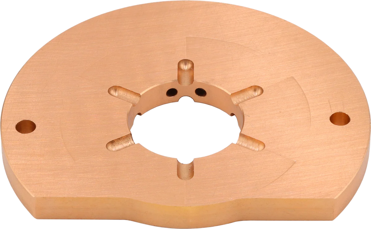
Thrust face: the oil film carries axial load.
Oil grooves: distribute lubricant across the working face.
Central opening: surrounds the shaft and collar region.
Product photograph from 2026. Numbers identify the features explained below.
Why many bearings use brass or bronze-type copper alloys
Many turbocharger thrust bearings use copper-based bearing alloys, including brass and bronze families. These terms cover different compositions and properties; they are not interchangeable material specifications.
A listing that says “brass alloy” tells you less about turbocharger thrust bearing materials than a documented specification from a reliable supplier. The alloy must combine suitable strength, wear behavior, thermal properties, and manufacturing consistency.
Three material characteristics matter in practice:
- Sliding compatibility: Suitable bearing alloys can reduce the tendency toward severe adhesive wear against the mating steel surface during brief periods of imperfect oil-film separation.
- Embeddability: Some bearing materials can accommodate small particles within their surface, limiting damage to the mating part. This ability varies considerably with alloy and hardness; a strong brass alloy should not be assumed to behave like a soft bearing lining.
- Heat conduction: Copper alloys can conduct heat away from loaded regions. Together with circulating oil and the surrounding structure, this helps control local film temperature and preserve viscosity.
Embeddability does not make dirty oil acceptable. Particles can still cut grooves, damage the collar, and disrupt the film. Likewise, thermal conductivity cannot compensate for a blocked oil feed.
Harder is not automatically better. Increasing hardness may improve resistance to certain forms of wear while reducing the ability to accommodate debris or local contact. Bearing selection is a tribology problem—the interaction of surfaces, lubricant, and motion—not simply a contest of material strength.
Color is also an unreliable quality check. Similar-looking yellow components can have different compositions, finishes, and dimensional accuracy.
Load capacity, friction, and oil flow must work together
A larger working area can help support axial load, but bearing size is only one design variable. Pad proportions, taper geometry, operating radius, and lubrication all influence the result.
There are costs to increasing capacity. Shearing oil between stationary and rotating surfaces consumes power and produces heat. Depending on the design, adding working area or increasing its radius can increase frictional loss. A bearing chosen with excessive capacity may impose unnecessary drag.
Oil flow creates another trade-off. Fresh oil replenishes the film and removes heat. Grooves and feed passages must distribute that oil effectively, but they also occupy space that might otherwise support load. Poorly arranged passages can leave a large-looking bearing with inadequate lubrication where it matters.
More supply pressure is not a universal cure. The feed, internal passages, clearances, and drain must function as a system. Unspecified restrictor changes or thicker oil can introduce new problems.
For a rebuilder, the practical decision is to use a proven assembly for the intended turbo and operating conditions. Enlarging grooves or drilling extra holes without validated design information can undermine the bearing.
Comparing 270 vs 360 turbocharger thrust bearings
Repair kits often advertise either a 270° or 360° thrust bearing. Broadly, these labels describe the circumferential extent of the bearing arrangement.
A 270° design generally has an open sector. A 360 degree thrust bearing extends around the full circumference, although its actual working surface still contains segments, grooves, and oil passages. It is not necessarily one uninterrupted load-carrying ring.
The label does not establish load capacity by itself. A full-circle arrangement may provide additional useful bearing area, but that advantage depends on its geometry, lubrication, and matching components.
| Selection point | Standard 270° arrangement | Compatible 360° arrangement |
|---|---|---|
| Typical rebuild purpose | Restore an application designed around this configuration | Restore or upgrade an application with a validated full-circle assembly |
| Potential advantage | Suitable capacity with the intended packaging and friction characteristics | Additional working area or improved load distribution, depending on design |
| Parts compatibility | Must match the original bearing, collar, and housing requirements | May require a different collar, spacer, or related components |
| Oil-system needs | Correct feed, passages, and drainage remain essential | Additional coverage still requires effective oil distribution |
| Main buying mistake | Assuming standard means inadequate | Assuming full-circle coverage guarantees durability |
If you are considering a thrust bearing upgrade for a stock turbocharger, a correctly specified standard kit can be a sound choice. A 360° upgrade makes more sense when the turbo family has a documented compatible conversion and the intended operating conditions justify additional thrust capacity.
Changed wheel combinations or operating pressure ratios can change axial loading. Those changes deserve assessment of the complete turbo assembly; a boost number alone does not define thrust demand.
Repeated thrust failures are a reason to investigate, not automatically order an upgrade. Contamination, inadequate lubrication, damaged mating parts, or operation outside the turbo’s intended range can defeat either arrangement.
What thrust-bearing failure looks like
When the oil film becomes inadequate or contaminated, the working faces may develop scoring, smearing, or material loss. Damage can affect both the copper-alloy bearing and its rotating collar.
As wear increases axial clearance, the shaft assembly can move farther than intended. Severe movement may allow wheel contact or disturb sealing conditions. Oil leakage, smoke, reduced performance, and unusual noise are possible consequences, but none uniquely identifies thrust failure.
Useful inspection clues include:
- Circular grooves: Consistent with abrasive debris or damaged mating surfaces, though the complete assembly must be examined.
- Smeared or wiped areas: Evidence of surface distress that warrants investigation of lubrication, loading, and temperature.
- Heavy deposits: A reason to examine oil condition, heat exposure, and restricted passages.
- Uneven segment wear: A prompt to check seating, mating-face condition, alignment, and assembly accuracy.
- Excessive measured end play: Evidence that axial control is outside specification, requiring inspection of all parts that establish clearance.
- Wheel or housing rub marks: A sign of consequential damage that a bearing-only repair may not address.
Photograph the parts before cleaning. Deposits and wear patterns can provide clues that disappear during washing.
How to choose a turbocharger thrust bearing: rebuild checks
A repair kit replaces selected wear components. It does not restore a damaged shaft, distorted housing, or unsuitable oil supply.
Before choosing parts, confirm the exact turbo identification and determine why the previous assembly failed. For the rebuild itself, use these checks:
- Verify the kit contents. Match the bearing, collar, spacers, sealing components, and required hardware to the exact assembly.
- Inspect both mating surfaces. Check the collar for grooves, heat damage, burrs, and dimensional wear. Follow the replacement criteria rather than relying on appearance alone.
- Check oil passages. Confirm feed holes and grooves align as intended. Remove contamination using the specified cleaning process.
- Inspect the housing and shaft. Damaged seats or other out-of-spec components can prevent a new bearing from working correctly.
- Measure axial clearance. Use the prescribed assembly state, measuring method, and limits. Finger feel is not an acceptance test.
- Follow orientation and fastening instructions. Bearing faces, collars, and fasteners may have specific installation requirements.
- Address the vehicle’s lubrication system. Investigate contaminated oil, restricted supply, drain problems, and any identified cause of oil starvation.
- Complete the required balancing and verification. Replacing thrust parts does not establish rotor balance. Follow the turbo’s rebuilding requirements, including specialist balancing where required.
- Prime before startup. Follow the applicable lubrication and initial-start procedure so the rebuilt assembly receives oil promptly.
If specifications, suitable measuring equipment, or balancing services are unavailable, a correctly matched replacement CHRA may be more practical than rebuilding individual components.
Common Questions
Is a 360 degree thrust bearing always better than a 270° bearing?
No. A compatible, well-designed 360° arrangement can provide additional load capacity, but coverage alone does not establish performance. Pad geometry, oil supply, materials, and the matching collar matter. A correctly specified standard arrangement can be suitable for a stock application.
Are brass and bronze turbo thrust bearings interchangeable?
Not simply because both are copper alloys. Alloy composition, hardness, dimensions, surface finish, and oil passages must suit the turbocharger. Color and a generic material description cannot establish interchangeability.
Can I reuse the thrust collar with a new bearing?
Only if the rebuild procedure permits reuse and the collar passes dimensional and surface-condition checks. Grooves, heat damage, or an unsuitable surface can damage the replacement bearing. Some conversion kits require their own matching collar.
Does a 360° thrust upgrade increase boost or horsepower?
The bearing itself does not command more boost or create power. Its purpose is to support axial loading. Any performance benefit depends on the complete turbocharger and engine setup; bearing coverage alone cannot justify a power claim.
Does turbo whine prove the thrust bearing has failed?
No. Air leaks, wheel damage, imbalance, and other faults can produce noise. Thrust wear may eventually allow wheel contact, but diagnosis requires inspection and axial-clearance measurement rather than judging the sound alone.
What end play should a rebuilt turbo have?
Use the specification and measurement procedure for the exact turbocharger or approved rebuild assembly. There is no universal clearance for every turbo. Too little clearance can interfere with lubrication and thermal operation; too much can allow damaging axial movement.
What do turbocharger thrust collar grooves mean?
Wear grooves on a turbocharger thrust collar can indicate abrasive debris or damaged mating surfaces. Inspect the complete assembly, including both mating surfaces and oil passages, and check the collar for heat damage, burrs, and dimensional wear. Follow the specified replacement criteria, because an unsuitable collar surface can damage the new bearing.
Contact LeadTurbo with your turbocharger part number and symptoms for help identifying a suitable turbo thrust bearing repair kit, CHRA, or replacement turbocharger.