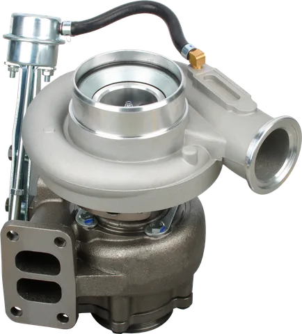
A turbo that bolts on or carries the right horsepower rating may still be wrong for sustained towing, generator load acceptance, or a repower. Learning how to choose a diesel turbocharger means checking the air supply, exhaust energy, and operating limits together. Start with the work the engine must do; wheel diameter comes later.
Where does diesel turbo sizing begin?
Record displacement, operating speeds, intended torque or power, fuel delivery, altitude, and intake temperature. Establish permitted cylinder pressure, exhaust temperature, and turbo speed from applicable engine and turbocharger specifications. Boost alone cannot define these limits.
For diesel turbo selection, duty cycle determines which points deserve priority:
| Application | Points to match | Practical priority |
|---|---|---|
| Truck or mobile equipment | Full-load rpm sweep and heavy lugging | Air supply during torque demand |
| Fixed-speed generator | Loads from light operation through rated output | Continuous efficiency and load-step response |
| Fixed-pitch marine propulsion | Points along the actual propeller load curve | Sustained operation and acceleration |
Build the requirements around these checkpoints:
- Include the lowest rpm at which the engine must carry heavy load.
- Include normal working points, not just rated output.
- Include expected hot-weather, altitude, and load-change conditions.
Estimate airflow from breathing and fueling
To estimate turbocharger airflow requirements for a four-stroke engine, calculate intake volume in liters per second as displacement in liters multiplied by rpm and volumetric efficiency, divided by 120. The divisor accounts for one intake stroke every two crankshaft revolutions and converts minutes to seconds.
That is volume at intake-manifold conditions. Multiply by manifold air density to obtain mass flow; density depends on absolute pressure and temperature. Define volumetric efficiency against those same conditions, rather than applying a boost correction twice.
Cross-check the result against fueling: required fresh-air mass flow is fuel mass flow multiplied by the target air-fuel ratio by mass. Use measured fuel delivery or an estimate based on power and brake-specific fuel consumption. Displacement alone cannot establish the fuel rate or required boost.
Choose the air-fuel target from validated engine data and combustion requirements. It is not a universal smoke-free setting. This simple approach assumes a four-stroke engine without EGR; recirculated exhaust and two-stroke scavenging require additional accounting.
Turn manifold pressure into compressor pressure ratio
The compressor must overcome the filter, inlet plumbing, charge cooler, and discharge piping. Its pressure ratio is absolute outlet pressure divided by absolute inlet pressure, using the pressure definitions specified for its map.
- Add charge-system pressure loss to the required manifold absolute pressure.
- Subtract inlet restriction from ambient absolute pressure.
- Divide the first result by the second.
Gauge boost is relative to local ambient pressure. At altitude, maintaining the same manifold absolute pressure requires a higher compressor pressure ratio. Check inlet temperature and turbo speed as well.
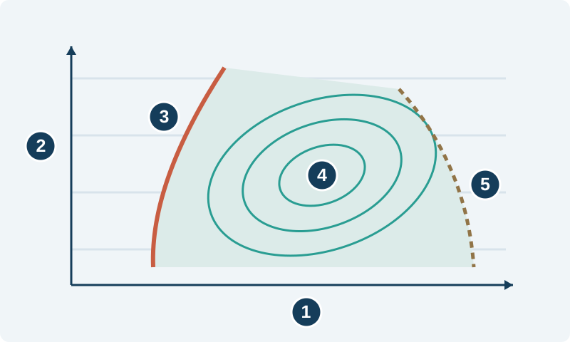
Horizontal axis: corrected air mass flow.
Vertical axis: absolute pressure ratio.
Low-flow boundary: surge limit.
Contours: efficiency islands inside the operating map.
High-flow boundary: choke region.
Qualitative schematic, not measured test data or operating limits.
Worked example: sizing a turbocharger for a diesel repower
These are assumed round numbers for an imaginary engine, not a recommended calibration or a turbo fitment claim:
- 6.0-liter four-stroke diesel at 2,200 rpm, with 90% volumetric efficiency.
- Fuel flow: 36 kg/h; selected air-fuel ratio: 24:1 by mass.
- Manifold air temperature: 330 K, approximately 57°C.
- Ambient pressure: 100 kPa absolute; compressor inlet: 95 kPa absolute at 300 K (a fairly loaded air filter; a clean system restricts less).
- Charge cooler and discharge plumbing loss: 15 kPa.
Breathing volume is 6.0 × 2,200 × 0.90 ÷ 120 = 99 liters/second, or 0.099 cubic meters/second. Fueling calls for 36 × 24 = 864 kg/h of air: 0.240 kg/s, approximately 32 lb/min.
Dividing 0.240 by 0.099 gives a required manifold density of about 2.42 kg per cubic meter. Applying the ideal-gas relationship at 330 K gives approximately 230 kPa absolute manifold pressure, or 130 kPa gauge boost at the assumed ambient pressure: about 19 psi.
Adding 15 kPa loss produces about 245 kPa at the compressor outlet. Dividing by the 95 kPa inlet pressure gives a required pressure ratio of approximately 2.58.
For an illustrative map referenced to 300 K and 100 kPa, with the assumed inlet also at 300 K, corrected flow is actual flow multiplied by 100/95. Different inlet temperatures require the map’s temperature correction too.
Add two assumed lower-speed fueling points while holding the other assumptions constant:
| Engine rpm | Fuel, kg/h | Actual air, kg/s | Corrected air, kg/s | Pressure ratio, rounded |
|---|---|---|---|---|
| 1,400 | 24 | 0.160 | 0.168 | 2.69 |
| 1,800 | 30 | 0.200 | 0.211 | 2.62 |
| 2,200 | 36 | 0.240 | 0.253 | 2.58 |
These are required demand points. They do not prove that a candidate turbocharger can supply them. Actual volumetric efficiency, temperature, and plumbing losses change with operating conditions.
If the real charge temperature is higher, achieving the same mass flow requires more manifold pressure. If cylinder filling falls because of backpressure, the pressure requirement rises again. Recalculate rather than assuming the initial point stays fixed.
Build operating lines, not a single winning point
Plot corrected airflow horizontally and pressure ratio vertically on the candidate’s compressor map. Use that manufacturer’s reference conditions and map units; an uncorrected airflow number can put the point in the wrong place.
Ask for the map for the exact compressor wheel and cover combination; a nearby model’s map is not a substitute.
The example table represents an assumed full-load demand line as engine speed changes. The lower-speed point asks for nearly the same pressure at much less flow, which can expose a surge problem hidden by the rated-power point.
Plot separate load sweeps for a generator running at governed speed. Its mass flow still changes as boost and intake temperature change. A fixed-pitch propeller follows a different load curve, with absorbed power often rising roughly with the cube of speed. Variable-pitch propulsion and mobile machinery need a broader operating envelope.
Favor good efficiency at the points where the engine spends its working hours. Leave supplier-supported clearance from surge, choke, and speed limits throughout the operating envelope. There is no universal surge-margin percentage that guarantees a sound installation.
Check transient behavior separately: a steady-state map cannot predict every acceleration or generator load step.
Check the turbine before calling the match complete
For this no-EGR example, total exhaust mass is approximately air plus fuel: 0.250 kg/s at rated output. A wastegate can bypass some of that flow around the turbine wheel.
Turbine selection also needs exhaust temperature, expansion ratio, efficiency, and the exhaust system’s downstream restriction. Ask for turbine flow data or a supplier-supported match for the proposed duty. A compressor map alone does not show whether the turbine can provide the necessary shaft power.
A restrictive turbine may deliver the requested boost while creating excessive exhaust manifold pressure and pumping losses. An overly generous flow area may leave insufficient shaft power at low speed. Validate both steady output and response.
Oversized vs undersized turbocharger: what goes wrong?
| Mismatch | Likely problem | Matching implication |
|---|---|---|
| Oversized compressor | Low-flow demand approaches surge at the required pressure ratio. | Check heavy-load, low-rpm points. |
| Undersized compressor | High-flow points approach choke, poor efficiency, or speed limits. | Check rated output and altitude demand. |
| Oversized turbine flow area | Weak low-speed boost and slower response. | Check available exhaust energy during load pickup. |
| Undersized turbine flow area | Excessive drive pressure and restricted high-load flow. | Check exhaust pressure and continuous-duty limits. |
Wheel size alone cannot diagnose the mismatch. A larger compressor and a restrictive turbine can combine poor low-speed behavior with excessive exhaust pressure at rated load.
Adjust housing or nozzle size with a clear purpose
Within a compatible turbine family, a smaller housing A/R or nozzle throat can improve low-speed response, but may increase high-load exhaust restriction. A larger passage can improve flow capacity while weakening low-speed response. A/R numbers from different turbine families are not direct capacity comparisons.
Use supported housing and nozzle combinations. Changing turbine geometry moves operating points but does not enlarge the compressor map. VGT control and wastegate settings must remain within validated limits; they cannot compensate for inadequate compressor capacity.
Know when to keep the OE specification
If fueling, power, controls, and duty remain standard, an OE part number or verified supersession is usually the sound choice. The original match accounts for much more than flange fit, particularly with electronically controlled turbochargers.
For a changed application, validate the proposed match under representative load before treating it as finished:
- Measure boost, intake temperature, exhaust manifold pressure, and exhaust temperature at defined locations.
- Check turbo speed against the manufacturer’s limit where measurement is available.
- Confirm load acceptance, smoke behavior, and control operation across the intended duty.
Without adequate maps, limits, or test data, a non-OE turbo remains an unverified choice.
Common Questions
Does more boost always mean more usable air?
Not necessarily. Hotter intake air is less dense, and added exhaust restriction can reduce cylinder filling. Compare air mass flow, charge temperature, and exhaust manifold pressure at the same operating point.
Is my turbocharger too big for low-speed work?
Check the low-speed demand points. A compressor may sit too close to surge at the required pressure ratio, while a large turbine may struggle to build shaft power quickly. Size each side separately.
Can a smaller turbine housing fix an oversized compressor?
It may improve response, but it cannot change the compressor map. If the required airflow and pressure ratio fall outside that map, a housing change cannot create a suitable compressor match.
Does a generator need the same match as a truck?
Not necessarily. A fixed-speed generator needs steady-load efficiency and acceptable load-step response. A truck must supply air through a wider speed range, including heavy fueling at low rpm.
When should I keep the OE turbocharger?
Keep the OE specification when the engine, fueling, controls, and duty remain standard. Consider a different match when documented operating requirements change and the complete system can be validated.
Can I size a diesel turbo from horsepower alone?
Horsepower is a starting clue. You also need the fuel rate, operating rpm, airflow target, pressure ratio, and duty cycle. Two engines producing the same power can need different compressor and turbine combinations.
What size replacement turbocharger do I need?
Keep the OE specification when the engine, fueling, controls, and duty remain standard. For changed requirements, match airflow and pressure ratio across the duty cycle and validate both sides of the turbocharger.
Contact us at LeadTurbo with your turbocharger part number, engine details, and intended duty to discuss replacement options.