For a pickup pulling away with a trailer or a passenger car accelerating out of a corner, the useful question is how quickly the engine delivers torque after the driver asks for it. A lightweight turbocharger turbine wheel can help, but its weight is only one part of that result.
Understanding where inertia comes from makes it easier to compare an OE-matched replacement with an upgraded turbocharger—and recognize when a claimed response improvement needs better evidence.
What turbine wheel inertia actually measures
A turbocharger’s rotating assembly includes the turbine wheel, shaft, compressor wheel, and associated rotating hardware. Its polar moment of inertia describes how strongly that assembly resists a change in rotational speed about the shaft axis.
Mass matters, but its location matters just as much. A small amount of material near the outer edge contributes more inertia than the same amount close to the shaft. Each portion’s contribution depends on its mass multiplied by the square of its distance from the axis.
That makes wheel diameter especially influential. Reducing diameter brings material closer to the axis and usually removes mass as well. However, changing diameter also changes the wheel’s ability to handle exhaust flow.
The turbine wheel commonly dominates turbo rotor inertia because it combines substantial mass away from the shaft centerline with a dense, heat-resistant nickel-based superalloy. The compressor wheel is usually made from a much lighter aluminum alloy, while much of the shaft’s mass sits close to the axis.
This is not an absolute rule. Compressor size, wheel geometry, and shaft construction affect the balance. The turbine does not have to be larger than the compressor to make the biggest contribution. Its material density and mass distribution can be enough.
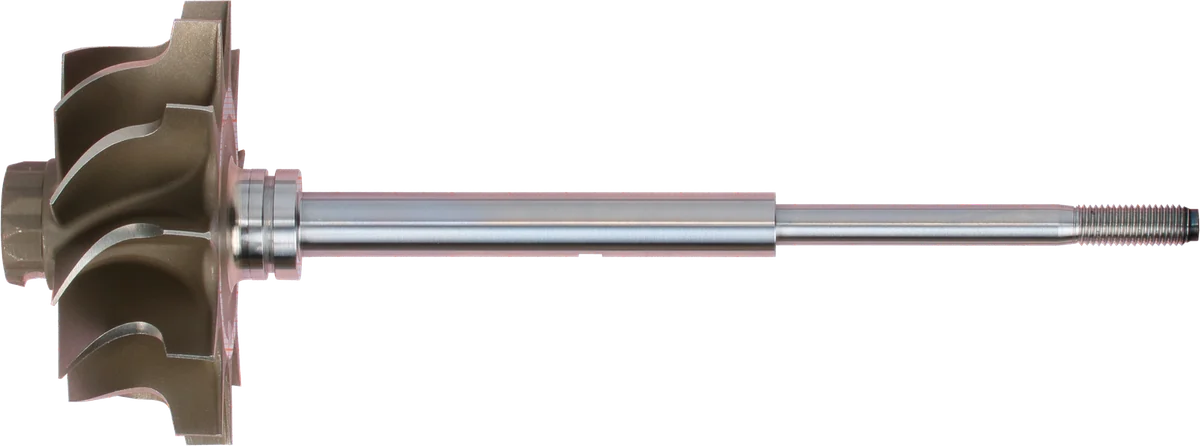
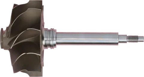
Turbine wheel: exhaust energy drives the shaft.
Shaft surface: inspect wear and scoring before reuse.
Shaft end: connects to the compressor-side rotating parts.
Product photograph from 2026. Numbers identify the features explained below.
Why Lower Inertia Can Improve Response
Exhaust gas applies driving torque to the turbine. The compressor consumes torque as it compresses air, and the bearings and other losses consume additional torque. Whatever remains accelerates the rotor.
With the same net accelerating torque, a lower-inertia rotor gains speed faster. But net torque changes throughout a real acceleration event as exhaust flow, pressure, compressor demand, and control positions change.
This explains why wheel weight alone cannot predict spool time. A lighter wheel that extracts less useful work from the exhaust may have less torque available to accelerate it. The inertia benefit and the aerodynamic penalty compete.
It also helps to separate two commonly confused behaviors:
- Boost threshold: The engine speed and load conditions at which the turbo can sustain useful boost.
- Transient response: How quickly boost and engine torque change after a demand change under specified starting conditions.
Lower inertia mainly helps during changes in rotor speed. It does not automatically make a large turbo produce useful boost at an engine operating point with insufficient exhaust energy.
Once rotor speed is steady, there is no continuing acceleration requirement. Efficiency, flow capacity, and mechanical losses then matter more than inertia itself.
How to Reduce Turbocharger Inertia and Improve Response
Several design choices can improve turbo transient response, but they work through different mechanisms.
| Change | How it can help | Main trade-off or limitation |
|---|---|---|
| Smaller turbine diameter | Reduces rotating mass and moves material closer to the axis | Can limit exhaust flow and increase backpressure at higher output |
| Scalloped turbine back face | Removes selected material from the rear of the wheel | May affect strength, stress distribution, and aerodynamic losses |
| Titanium aluminide turbine wheel | Reduces material density compared with conventional nickel superalloys | Requires suitable temperature capability, manufacturing quality, and application validation |
| Lower-friction bearing system | Leaves more turbine torque available for acceleration | Adds cost and may require different oil supply or installation provisions |
| Better turbine and housing matching | Improves useful torque from the available exhaust flow | Must balance response against flow capacity and the engine’s operating range |
Lower-friction bearings belong in a response comparison, but they do not inherently reduce turbine wheel inertia. They change the losses the turbine must overcome.
Smaller Diameter: Useful Within a Defined Power Range
A smaller turbine can be a sensible match for an engine that prioritizes low- and midrange operation. The problem appears when the engine’s exhaust flow demand exceeds what that turbine and housing can handle efficiently.
Higher exhaust backpressure can increase engine pumping work and reduce the benefit of an otherwise responsive setup. Sustained towing and repeated high-load operation therefore deserve attention alongside a quick acceleration test.
Evaluate wheel diameter together with housing geometry and turbine flow capability. Diameter alone does not tell you how restrictive the complete turbine stage will be.
Scalloped Back Faces: More Than Removing Weight
A scalloped back face removes selected portions of material behind the turbine blades. Its value depends on where material is removed: weight reduction farther from the axis has a greater effect on inertia.
The remaining structure still has to survive rotational and thermal stresses. Rear-face geometry can also change gas movement and losses around the wheel.
A well-developed design can offer a useful compromise. Aggressively removing material from an existing wheel without engineering validation is not an equivalent upgrade.
What to Know About a TiAl Turbine Wheel
Titanium aluminide, commonly shortened to TiAl, is attractive because it is substantially less dense than the nickel-based superalloys commonly used for turbine wheels. In a suitable design, that can reduce the turbine’s contribution to rotor inertia.
TiAl is a distinct material family. It should not be treated as interchangeable with conventional titanium alloys, and a vague “titanium wheel” description does not establish suitability for exhaust-side service.
Temperature capability depends on the actual alloy, manufacturing process, wheel design, and duty cycle. Resistance to oxidation, creep, thermal cycling, and crack growth all matter. A material suitable for one engine’s exhaust conditions may be unsuitable for another application.
Durability also involves more than surviving a temperature limit. Foreign-object damage tolerance, casting quality, the wheel-to-shaft connection, and inspection standards are relevant.
For buyers, the useful questions are specific:
- What material is actually used?
- Is the wheel validated for this engine and intended duty?
- What operating limits apply?
- Who manufactures and balances the assembly?
- What support is available if inspection or replacement becomes necessary?
Expect material and manufacturing choices to affect cost. Lower density is a benefit, not proof of a better complete turbo.
Why Ball Bearings Often Help More at Low Speed
Ball bearings can reduce mechanical losses compared with some oil-film bearing arrangements. Their response benefit is often most noticeable when the turbine has relatively little power available.
During initial acceleration from low turbo speed, bearing losses can consume a meaningful portion of the available driving power. Reducing those losses leaves more power to increase rotor speed.
At higher turbo speed and load, turbine power and compressor demand are much greater. Bearing losses often represent a smaller share of the overall power balance, so a reduction in those losses may produce a smaller relative improvement.
That does not mean bearing friction disappears at high speed, or that every bearing design performs identically. Oil viscosity, temperature, supply conditions, thrust load, and bearing construction all influence losses.
Cold oil can also change the comparison. Follow the specified lubricant and warm-up guidance rather than choosing thinner oil solely to chase response.
A ball-bearing turbo can still respond poorly if its turbine is oversized for the engine. Likewise, a properly matched journal-bearing turbo can deliver strong practical response. Compare complete assemblies under comparable conditions.
OE-Matched Turbocharger Replacement vs Upgrade
Start with the job the vehicle needs to do.
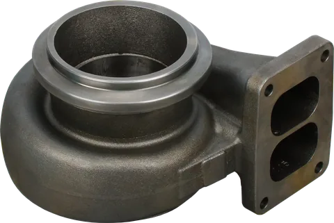
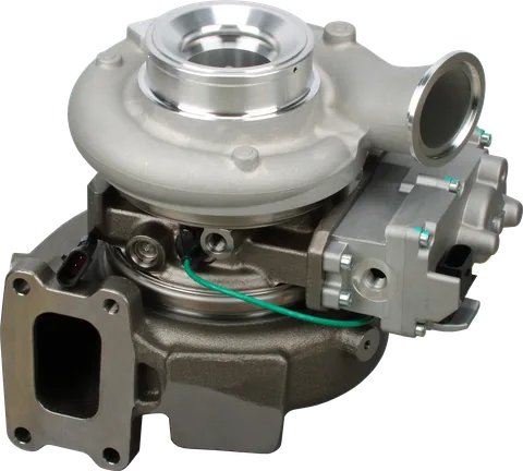
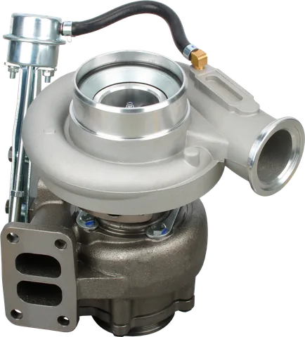
An OE-matched replacement is usually the straightforward choice for restoring expected drivability on a stock vehicle. Matching includes the turbine and compressor configuration, housings, actuator, and control behavior—not merely the mounting flange.
An upgrade makes more sense when there is a defined performance objective and supporting information. “Faster spool” should be tied to an operating condition, such as acceleration from a particular engine speed in the same gear, rather than an unexplained marketing claim.
Useful comparison evidence keeps these factors consistent:
- Engine hardware, fuel, and calibration.
- Starting engine speed, gear, and load.
- Boost target and throttle demand.
- Ambient and engine operating temperatures.
- Measurement method and the point considered fully responsive.
Ask whether the comparison measures boost, turbo shaft speed, or engine torque. They are related, but they are not interchangeable. A fast pressure rise does not always produce an equally fast increase in usable torque.
Prioritize sustained operating suitability alongside turbocharger response for towing. For a performance build, consider whether improved low-speed behavior comes at the expense of the airflow needed for the power target.
Calibration Is Part of the Hardware Match
A different turbine can change the relationship between exhaust flow, shaft acceleration, and boost. Existing wastegate or variable-geometry control commands may no longer produce the intended result.
Depending on the change, the system may need calibration work to manage boost rise, overshoot, vane position, or torque delivery. Physical fit does not establish control compatibility.
An OE-matched replacement generally retains factory calibration compatibility, although actuator setup or relearn procedures may still apply.
For a CHRA or core purchase, confirm compatibility with both housings and the control system. A repair kit does not convert an existing turbo into a validated lightweight-wheel or ball-bearing design.
Does Turbine Inertia Cause Slow Turbocharger Response?
A turbo that has become slower to respond has not normally gained meaningful inertia. Look for a change in operating condition or component health first.
Useful inspection points include:
- Charge-air leaks at hoses, clamps, and the intercooler.
- Exhaust leaks upstream of the turbine.
- Wastegate or variable-vane movement and actuator operation.
- Intake restrictions and application-specific exhaust restrictions.
- Wheel damage, housing contact, or abnormal shaft movement.
- Oil supply, drain condition, and correct lubricant.
- Fault codes and differences between requested and measured boost.
Follow service information for inspection limits. Shaft movement and hand-spin feel alone are not reliable ways to compare bearing efficiency or predict loaded response.
Correcting a leak or control fault may restore the response the original turbo was designed to provide. Establishing that baseline also makes an upgrade decision more meaningful.
Common Questions
Does a lighter turbine wheel always spool faster?
Lower inertia helps when the torque available to accelerate the rotor stays the same. A lighter wheel that extracts less exhaust energy can lose some or all of that advantage. Compare the complete turbo and its intended operating range, not wheel weight alone.
Is a TiAl turbine wheel the same as a titanium wheel?
TiAl means titanium aluminide, a distinct material family with different properties from conventional titanium alloys. A listing that only says titanium is incomplete. Ask for the actual material, application suitability, and temperature limits.
Will ball bearings eliminate turbo lag?
No. Ball bearings can reduce bearing losses, especially when available exhaust power is low, but they cannot supply missing exhaust energy or correct an oversized turbo. Engine controls, turbine sizing, and the intake system still affect response.
Can I install a lightweight turbine wheel in my existing turbo?
Only as part of a properly engineered rebuild. The wheel and shaft must suit the housing, bearings, clearances, and operating limits, and the rotating assembly requires appropriate balancing. A wheel that physically fits is not necessarily a safe or effective match.
Does an OE-matched replacement need a performance tune?
A correctly specified OE-matched replacement generally works with the factory engine calibration. Application-specific actuator setup, adaptation, or relearn procedures may still be required. A turbo with different flow characteristics or control hardware needs a separate calibration assessment.
Does faster boost response mean more peak horsepower?
No. Faster response describes how quickly the system reaches an operating condition. Peak power depends on sustained airflow, pressure, efficiency, and engine limits. A smaller turbine may improve response while restricting exhaust flow at higher engine output.
Contact LeadTurbo with your turbo part number, vehicle details, and symptoms for help identifying a suitable replacement or discussing turbine wheel inertia and your upgrade requirements.