A replacement wheel earns its place through measured performance at the engine's working points. For a loaded truck or a generator carrying steady load, diesel turbocharger efficiency means producing the required airflow and pressure with manageable heat and shaft power demand.
What does turbo efficiency actually measure?
For a stated pressure ratio, turbocharger compressor efficiency compares the ideal compression work with the actual work added to the air. A less efficient compressor produces a larger temperature rise for the same pressure ratio and inlet temperature. Pressure ratio uses absolute pressures at the compressor inlet and outlet.
That extra heat increases the intercooler's job and reduces air density at a given pressure before cooling. Supplying the extra compressor power also burdens the turbine. Depending on the turbine match and boost control, maintaining the same duty can require higher exhaust manifold pressure and more engine pumping work.
As an illustrative comparison, consider two compressors delivering equal airflow and pressure ratio under identical inlet conditions. The cooler discharge generally indicates less compression work, provided heat transfer and measurement methods are comparable. Measuring temperature after the intercooler would obscure this comparison.
A compressor rating describes only one stage. Turbine performance and mechanical losses also affect the complete turbocharger. Compare efficiency claims at the same airflow and pressure ratio, using consistent test definitions.
Turbocharger wheel design: blade outlet angle trade-offs
Viewed along the shaft, the blade's outlet direction describes how it meets the wheel's outer edge. Radial, backswept and forward-curved exits change the work transferred to the air. These tendencies assume comparable tip speed, throughflow and inlet conditions.
| Outlet type | Pressure-rise potential | Efficiency and map width | Stress considerations |
|---|---|---|---|
| Radial: points outward from the center | Relatively high work input at a given tip speed | Efficiency and useful range depend strongly on loading and diffuser design | Direct radial loading can simplify structural design |
| Backswept: trails the direction of rotation | Lower work input at comparable speed; achieving a target pressure may require more speed | Often supports good efficiency and a broad useful range when properly matched | Sweep can add bending loads requiring adequate blade and root strength |
| Forward-curved: bends toward rotation | Higher work potential, with more exit swirl to recover | Greater diffusion demand can limit efficiency and usable range; uncommon in turbocharger compressors | Curved blades and roots need specific bending and fatigue checks |
Actual pressure rise depends on how well the wheel and diffuser convert that work into pressure. A backswept compressor wheel can support high pressure ratios when its speed capability and overall design allow it.
Increasing speed to recover pressure also raises centrifugal loading. Blade thickness, root fillets and the rear disk shape must support the design speed and fatigue duty. Aerodynamic changes therefore need structural validation.
Outlet backsweep also differs from blade lean through the wheel's depth. A forward-leaning blade does not necessarily have a forward-curved outlet.
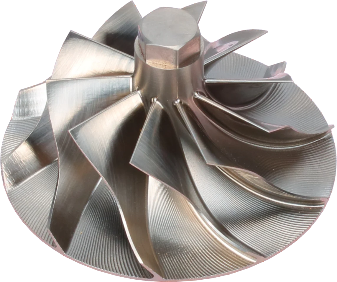
Blades: inspect for chips, bends and contact marks.
Hub: part of the balanced rotating assembly.
Outer blade tips: check for housing rub.
Product photograph from 2026. Numbers identify the features explained below.
The hidden importance of the meridional flow path
Imagine slicing the compressor lengthwise through its shaft. The hub contour and the surrounding shroud contour outline the meridional flow path: the route from axial entry to radial discharge. Passage area also depends on circumference and blade blockage; its design must account for changing air density.
Designers must coordinate these features. A local pinch or sudden opening makes the air accelerate or decelerate unevenly. If deceleration is too aggressive, slow air near a wall can separate, leaving recirculating pockets that mix with the main stream and waste energy.
The edges and junctions matter as much as the broad outline. An outlet step between the wheel and diffuser can leave a separated region, while an inlet lip or oversized obstruction can distort flow before it reaches the blades.
Sharp turning causes additional secondary flows across the passages. Compact, short wheels save weight but force a tighter turn, which costs efficiency. Small changes in hub shape, blade height or housing contour can therefore matter even when the headline wheel diameters stay unchanged.
Off-design entry, swirl and tip leakage
Air must meet a moving blade at a suitable angle. Change airflow or shaft speed, and the relative entry direction changes. Poor alignment, called incidence, can cause leading-edge separation and mixing. These are sometimes called shock losses, although they can occur without a supersonic shock wave.
Both low-flow and high-flow operation can move the compressor away from its preferred incidence. Vaned diffusers have their own entry-angle sensitivity. This is one reason a wheel chosen mainly for maximum airflow may disappoint during ordinary loaded operation.
A tight inlet elbow, abrupt reducer or poorly aligned connection can deliver uneven velocity and unwanted inlet swirl. At discharge, swirling flow is expected; losses grow when its motion is poorly recovered or uneven streams mix.
Tip leakage adds another loss. Air crosses the clearance from a blade's high-pressure side to its low-pressure side, disturbing the main flow. Worn tips or a mismatched housing contour can increase that leakage.
Losses behind the wheel and inside the housing
Several turbo flow losses occur outside the blade passages. A wheel's performance depends on the stationary parts surrounding it. The diffuser slows the discharge to recover static pressure; the volute collects that flow into the outlet.
| Location | Where useful energy goes | What matters in a replacement |
|---|---|---|
| Wheel back face | Disk friction and windage: the rotating surface shears and circulates gas in the back cavity, consuming torque | Correct back-face profile, cavity geometry and running clearances |
| Diffuser | Wall friction, poor entry alignment and separation during deceleration reduce pressure recovery | Compatibility with wheel exit height, discharge angle and flow range |
| Volute | Uneven collection, unsuitable area changes and disturbances near the tongue cause mixing and pressure loss | Accurate internal casting shape and a smooth transition to the outlet |
A vaned diffuser can provide strong pressure recovery near its intended duty, but changing incidence can reduce that advantage elsewhere. Vaneless designs have different compromises in friction, recovery and operating range. Either type needs to suit the wheel.
Back-cavity modifications are also engineering changes. Machining away material or changing a backplate affects clearances and flow, with consequences beyond rotor weight.
How to improve turbocharger efficiency across the system
Improving turbo efficiency requires an exhaust side that supplies shaft power efficiently. Turbine blades also suffer incidence, sharp-turning, leakage and wall-friction losses. Nozzle passages, the housing and blade geometry must guide expansion smoothly. Residual outlet swirl carries away energy that the shaft has not recovered.
Damaged turbine blades and poor internal castings can disturb that process. Depending on operating conditions, delivering the same compressor power may then require more exhaust pressure. Turbine back-cavity windage adds another parasitic load.
Outside the turbocharger, a restricted air filter lowers compressor inlet pressure. Charge-pipe, intercooler and intake-manifold pressure drops increase the compressor discharge pressure needed to achieve a target manifold pressure. Both conditions raise the compressor's required pressure ratio.
Exhaust leaks before the turbine lose drive energy; restrictive passages before or after it also hurt performance. A turbine outlet restriction reduces available expansion at a given inlet pressure. Manifold design must handle pulsating flow, so smooth bends and sensible transitions belong within an engine-specific design.
How to judge a replacement turbocharger compressor wheel
Start with the validated wheel and housing combination for the application. Two wheels can share their main diameters yet differ in blade thickness, splitter shape, exit width, tip contour and back-face geometry. Each difference can change flow or mechanical loading.
Billet (machined from forged stock) wheels mainly offer consistent geometry and better fatigue strength at high speed. They are not more efficient by default; any gain comes from the blade design itself.
When comparing billet vs cast turbocharger compressor wheels, manufacturing quality matters because flash, rough passage surfaces, distorted contours and damaged leading edges can create blockage, separation or extra friction. A casting with the correct aerodynamic geometry can outperform a precisely machined wheel with an unsuitable design.
| Seller claim | Evidence worth requesting | Practical reason |
|---|---|---|
| Higher efficiency | Comparison data at the same pressure ratio, corrected flow and test conditions | A peak figure may miss the engine's normal duty |
| Direct replacement | Confirmed wheel, housing and backplate compatibility | Matching diameters alone leave important geometry unverified |
| More flow | A map for the exact compressor combination, including speed limits | Extra capacity helps only where the engine can use it |
A steady-load generator and a delivery truck occupy different parts of a compressor map. Request evidence covering the actual duty cycle, including sustained load and transitions.
Before accepting the part:
- Check leading edges, blade tips and passages for damage, flash, rub marks and obvious profile inconsistencies.
- Verify specified running clearances, allowing for thermal and centrifugal growth.
- Request traceable manufacturing information and speed or durability validation for a changed design.
- Treat balancing documentation as evidence of rotor preparation; aerodynamic performance needs separate support.
For a standard rebuild, faithful replacement geometry is a sound starting point. An upgrade needs stronger evidence that it improves the required working range while respecting the assembly's speed and stress limits.
Common Questions
Does higher boost prove better compressor efficiency?
No. Boost shows pressure at the measurement point. A useful comparison also needs airflow, inlet conditions, outlet temperature and shaft speed. Extra boost can come with more heat and turbine power demand.
Can a backswept wheel produce high pressure?
Yes. Backsweep reduces work input at a comparable tip speed, but a complete design can reach high pressure ratios through appropriate speed and geometry. Its speed limit, housing match and tested operating range still matter.
Does a small blade nick matter?
It can. A nick can disturb local flow and create a stress concentration. The effect depends on its location and size, so appearance alone cannot establish serviceability. Follow the manufacturer's damage limits.
Will polishing a wheel recover lost performance?
Polishing cannot correct unsuitable passage geometry or housing mismatch. Removing material can alter blade shape, clearances and balance. Use approved repair procedures and validated replacement parts.
Is a compressor map enough to judge an upgrade?
It is useful only when it represents the proposed wheel and housing combination. Check the engine's working points, test definitions and speed limits, then consider turbine capability and system pressure losses.
Will a billet wheel improve turbo efficiency?
Possibly, but the manufacturing label alone proves no aerodynamic gain. Any improvement must come from suitable geometry, consistent production and a tested match to the housing and engine's operating range.
Why is turbocharger outlet temperature high?
At the same pressure ratio and inlet temperature, a less efficient compressor produces a larger temperature rise. Compare temperatures before the intercooler, with comparable airflow, heat transfer and measurement methods.
For help selecting a replacement wheel or turbocharger, contact LeadTurbo with your turbo part number, engine details and application.