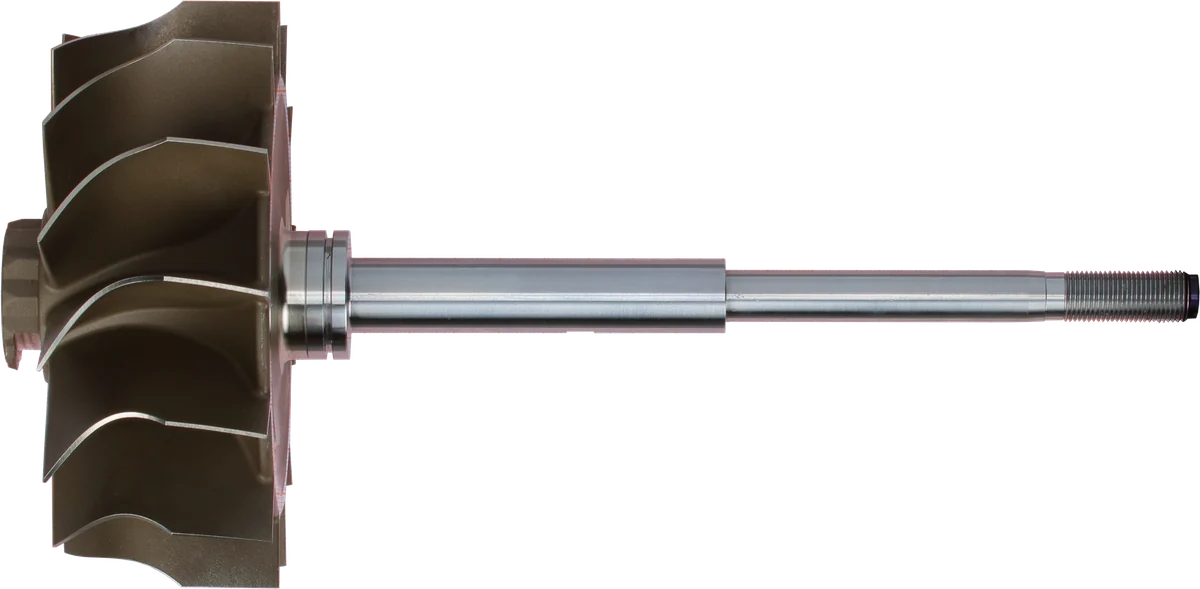
Understanding turbo critical speed vs maximum speed
A turbocharger rotor does more than spin. Its centerline can move sideways, tilt, and bend while the wheels continue rotating. Bearings and the shaft resist those movements, creating a system with preferred vibration patterns and frequencies.
A critical speed occurs when a speed-related excitation matches a compatible natural vibration mode. For the familiar unbalance response, the excitation repeats once per shaft revolution. Near a matching mode, even a small residual unbalance can produce a noticeable increase in movement.
This is different from a turbo’s maximum allowable speed. Critical speed describes a resonance condition; it does not establish the wheel’s strength limit or a safe operating ceiling.
There is also no universal diesel turbocharger critical speed or single critical speed for a replacement CHRA. The relevant behavior belongs to a particular rotor, bearing arrangement, and operating condition.
Natural Frequencies and Rotor Mode Shapes
A rotor natural frequency is a frequency at which the supported assembly tends to vibrate after a disturbance. Turbocharger rotor mode shapes describe how the assembly’s different parts move during that vibration.
Think of frequency as the rhythm and mode shape as the movement pattern. Two modes can involve very different shaft motions, even when their frequencies are relatively close.
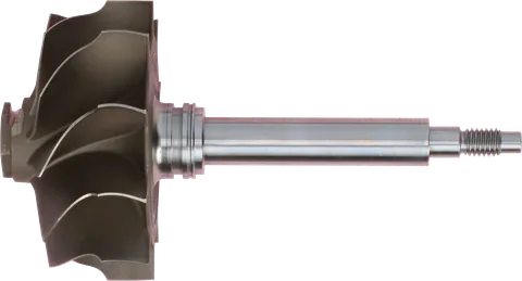
For a turbocharger, the important assembly includes the wheels, shaft, bearings, and their support characteristics. In a journal-bearing turbo, the oil films contribute stiffness and damping, so the rotor cannot be understood as a bare shaft alone.
| Mode | What the movement looks like | Practical significance |
|---|---|---|
| Cylindrical rigid-body mode | The rotor moves sideways with its centerline remaining approximately parallel to its original position. | Bearing support properties strongly influence the motion. |
| Conical rigid-body mode | The rotor rocks or tilts, with opposite ends generally moving in opposite directions. | Wheel inertia, bearing spacing, and support behavior affect the response. |
| Bending mode | The shaft itself curves as different sections move by different amounts. | Shaft geometry and wheel properties become especially important. |
“Rigid-body” does not mean that the assembly is infinitely stiff. It means shaft bending is small enough that translation or rocking describes the mode reasonably well.
Real turbo rotors are not perfectly symmetric. Their compressor and turbine ends differ, so a measured or calculated mode may combine translation, tilt, and bending. The table gives useful mental pictures, not three perfectly separate behaviors in every turbo.
How to Read a Turbocharger Campbell Diagram
A Campbell diagram puts rotor speed on the horizontal axis and vibration frequency on the vertical axis. It shows how natural frequencies change as the rotor accelerates.
Those natural-frequency curves are plotted alongside excitation lines:
- 1X: One vibration cycle per shaft revolution, commonly associated with unbalance.
- 2X: Two cycles per revolution, relevant when a twice-per-revolution excitation is present.
- Other orders: Additional multiples or fractions of shaft frequency, included when relevant to the mechanism being investigated.
If speed is shown in rpm and frequency in hertz, the 1X line follows shaft speed converted to revolutions per second. Both axes must be interpreted using their stated units.
Where an excitation line crosses a natural-frequency branch, the frequencies match. A compatible 1X crossing identifies a candidate synchronous critical speed.
However, a crossing alone does not tell you how much the rotor will move. That requires information about forcing, damping, mode shape, and how effectively the excitation drives that mode. A frequency plot is a map of possible resonance conditions, not a vibration acceptance report.
When reviewing a Campbell diagram for a turbocharger, check:
- Which rotor and bearing configuration the model represents.
- Whether frequencies use a stationary or rotating reference frame.
- Whether the branches are labeled by mode and whirl direction.
- Where the actual operating range lies.
- What oil temperature and bearing conditions were assumed.
- Whether response and stability results accompany the frequency plot.
Also distinguish a calculated Campbell diagram from a measured frequency-versus-speed color map. They can look similar, but one predicts modes while the other displays recorded vibration or noise.
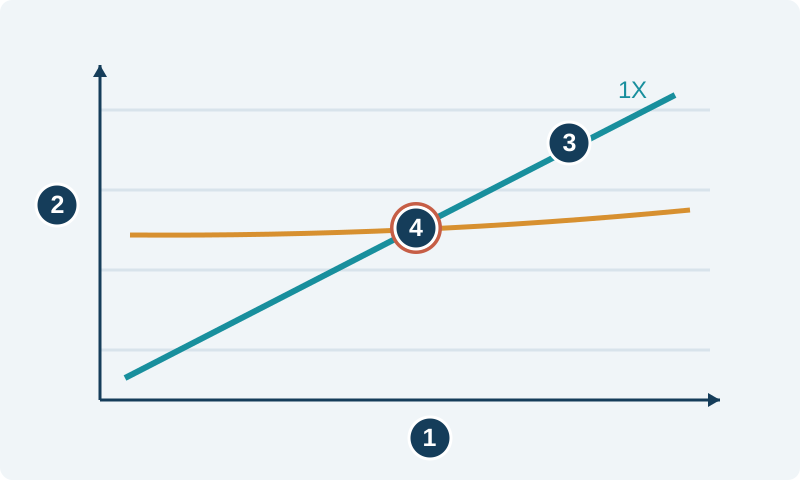
Horizontal axis: shaft speed.
Vertical axis: vibration frequency.
1X excitation follows shaft rotational frequency.
A crossing with a mode can identify a resonance risk.
Qualitative schematic, not measured test data or operating limits.
Why the Frequency Curves Split as Speed Rises
The compressor and turbine wheels act like gyroscopes. Their resistance to changes in orientation depends on rotational speed and how their mass is distributed around the shaft.
This matters because rotor vibration can include whirl: movement of the shaft centerline around its average position. Whirl direction is separate from the direction in which the shaft surface spins.
In forward whirl, the centerline motion travels in the same direction as shaft rotation. In backward whirl, it travels in the opposite direction.
Gyroscopic effects can separate otherwise paired modes into forward and backward branches. In a common stationary-frame presentation, the forward branch rises and the backward branch falls as speed increases. Actual curve shapes also depend on bearings, geometry, and the mode involved.
Modes involving substantial wheel tilt generally show stronger gyroscopic influence than nearly pure sideways translation.
Ordinary rotating unbalance predominantly excites forward whirl in an ideal symmetric system. Consequently, a backward-branch crossing is not automatically another strong unbalance resonance. Asymmetry, contact, and other forcing mechanisms can complicate that picture.
This is why reading every line intersection as a failure point gives misleading conclusions.
Why Does Turbocharger Vibration Peak During Acceleration?
A turbo does not instantly settle into the steady vibration response associated with each shaft speed. During acceleration, it passes through a changing set of conditions, and vibration takes time to build or decay.
When the rotor crosses a resonance, the observed peak depends on residual unbalance, damping, and how quickly the speed changes. A faster passage can limit the time available for vibration to grow. It does not guarantee harmless motion.
The largest transient response may also occur slightly after the nominal crossing. A run-down trace can differ from a run-up trace because the speed history and bearing conditions differ.
For a shop reviewing a controlled test, that means a narrow vibration peak should be interpreted alongside the sweep rate, oil conditions, and measurement setup. Comparing two reports without those details may produce a false diagnosis.
Do not try to locate resonance by holding an installed engine at a troublesome sound or repeatedly forcing boost. Engine rpm is not turbo shaft rpm, and vehicle testing does not provide the controlled conditions needed for a reliable rotor assessment.
Why Designers Separate Bending Resonance From Operation
A rotor bending mode can produce substantial movement at the wheels, making it particularly important where running clearances are small.
Designers aim to place significant turbocharger bending resonances outside the intended operating range, often by keeping the first bending critical speed above it. The desired separation must account for the assembled system and changes in bearing behavior.
That does not mean every natural mode must lie above every speed the turbo encounters. Lower support-dominated modes may be crossed during acceleration. Whether that is acceptable depends on the resulting motion and the system’s stability.
Oil-film damping helps control vibration by dissipating energy as the rotor moves. In floating-ring bearing designs, oil films around the bearing ring contribute to this behavior as well.
But an oil film is not simply a vibration cushion. Under some conditions, fluid-film forces can feed energy into rotor motion and cause instability.
Oil whirl is typically subsynchronous: its frequency is below shaft rotational frequency, often around half of it or less. The relationship depends on the bearing system. Oil whip involves motion becoming tied to a rotor natural frequency rather than continuing to track shaft speed proportionally.
These mechanisms explain why a satisfactory 1X response does not establish complete rotor stability. Designers need suitable mode placement, controlled response, and stable bearing behavior.
What This Means for Rebuilding and Buying Parts
The practical lesson is to preserve or properly validate the complete rotating assembly. A component can fit physically while changing how the rotor behaves dynamically.
Balance Quality Controls the Excitation
Better balance reduces the once-per-revolution force that drives synchronous vibration. It generally reduces resonance response, but it does not eliminate the natural mode itself.
Component balance and assembled-CHRA vibration testing answer different questions. Ask what was balanced, whether the assembled unit was tested, and what acceptance criteria were used.
A low reading at one speed is not a complete picture if a significant response occurs elsewhere in the tested range.
Bearing Clearances Affect the Support
Bearing clearances influence oil-film stiffness, damping, and stability. Wear, incorrect parts, or unsuitable machining can therefore change the response even when the rotor’s balance has not changed.
Tighter is not automatically better. Clearances must match the design and allow proper lubrication and thermal behavior.
During inspection:
- Check for wheel contact, shaft damage, and contaminated oil.
- Measure specified bearing and thrust clearances using the appropriate procedure.
- Inspect the oil supply and drain for restrictions.
- Confirm the specified lubricant and installation requirements.
- Interpret hand-felt radial movement according to the bearing design.
A dry journal-bearing assembly can have perceptible movement; that observation alone cannot establish its running condition.
Wheel Upgrades Change More Than Airflow
A larger or differently shaped wheel changes mass distribution and rotational inertia. It can shift natural frequencies, alter mode shapes, and change gyroscopic splitting.
The result cannot be predicted reliably from wheel diameter alone. Shaft geometry, wheel overhang, bearing properties, and the other wheel all matter.
Successful balancing does not prove that a modified rotor has acceptable bending-mode separation or stable bearings. For an upgrade, ask for validation of the actual wheel, shaft, and bearing combination.
When selecting a replacement CHRA or repair kit, match the turbo identification and assembly specification. Similar appearance is insufficient evidence of dynamic compatibility.
Common Questions
Is turbo critical speed the maximum safe shaft speed?
No. Critical speed concerns resonance between an excitation and a rotor mode. Maximum allowable shaft speed also depends on wheel strength, temperature, bearings, and other design limits. A critical-speed calculation cannot establish a safe overspeed limit.
Can turbo resonance occur despite proper balancing?
Yes. Balancing reduces the force that excites synchronous vibration, but it does not remove the rotor’s natural modes. Residual unbalance, other forcing, and bearing behavior still matter. Good balance and suitable damping work together.
Does every Campbell diagram crossing mean trouble?
No. A crossing identifies a possible resonance condition. The excitation must couple to that mode, and the resulting motion depends on force level, damping, and operating conditions. Response and stability assessments determine whether the crossing matters.
Will a larger compressor wheel change critical speed?
It can. Wheel mass, mass distribution, and inertia affect the rotor’s modes and gyroscopic behavior. The direction and size of the change depend on the complete assembly. A successful balance check alone does not validate an upgraded rotor design.
Is oil whirl the same as a 1X critical speed?
No. Oil whirl is a subsynchronous instability associated with fluid-film bearing forces. A 1X critical speed concerns excitation at shaft rotational frequency meeting a compatible natural mode. Both can cause vibration, but they require different diagnostic reasoning.
Can I identify turbo critical speed from a whistle?
Not reliably. A whistle may involve rotor vibration, airflow, leakage, or another source. Identifying a critical-speed response requires shaft-speed information and suitable vibration measurements, ideally with amplitude and phase tracked through a controlled speed sweep.
How do I choose a turbocharger CHRA?
Choose a CHRA that matches your turbo identification and assembly specification. A unit can fit physically while changing how the rotor behaves, so appearance alone is not enough. Ask what was balanced, whether the assembled unit was tested for vibration, and what acceptance criteria were used.
For help identifying replacement options, contact LeadTurbo with your turbocharger part number, vehicle details, and symptoms.