Begin with the engine's duty and mounting arrangement
When a crack calls for diesel turbocharger exhaust manifold replacement, first establish whether the existing arrangement served the engine correctly before the failure. A work truck repeatedly pulling away under load needs useful response at low speed. A generator operating near one speed may place greater emphasis on sustained flow and durability. A fabrication project needs both evaluated across its intended duty cycle.
Record the engine identification, rated output, turbocharger part number, turbine inlet style, and manifold casting number. Check the turbo mounting position, nearby hoses, service access, and supports. An aftermarket casting can share a bolt pattern while changing internal passages, outlet position, or expansion arrangements.
- Match the head ports, outlet orientation, gasket openings, and any required EGR or sensor connections.
- Preserve the intended cylinder grouping and turbine inlet divider.
- Check clearance for movement when hot as well as clearance during cold assembly.
What should a turbo exhaust manifold actually do?
Exhaust leaves a diesel cylinder in an initial pressure-driven burst, followed by gas pushed out during the exhaust stroke. The manifold must carry that changing flow with useful pressure and heat remaining at the turbine. Average flow capacity alone cannot describe how it behaves.
Exhaust valve opening timing sets the starting conditions. Opening earlier can release gas at higher pressure, but it gives up some expansion work at the piston. Opening later retains more expansion work while leaving less time for the cylinder to empty. Valve lift and opening rate affect how quickly the first burst escapes.
Those are engine design choices. An oversized collector cannot correct a valve timing error or insufficient valve lift. For a repower, retain the specified valve timing unless the complete engine combination has been engineered and validated for a change.
Higher pressure at the turbine can support more turbine work. Higher pressure against the piston during exhaust also costs work. The design must balance turbine energy delivery with the work required to empty the cylinders.
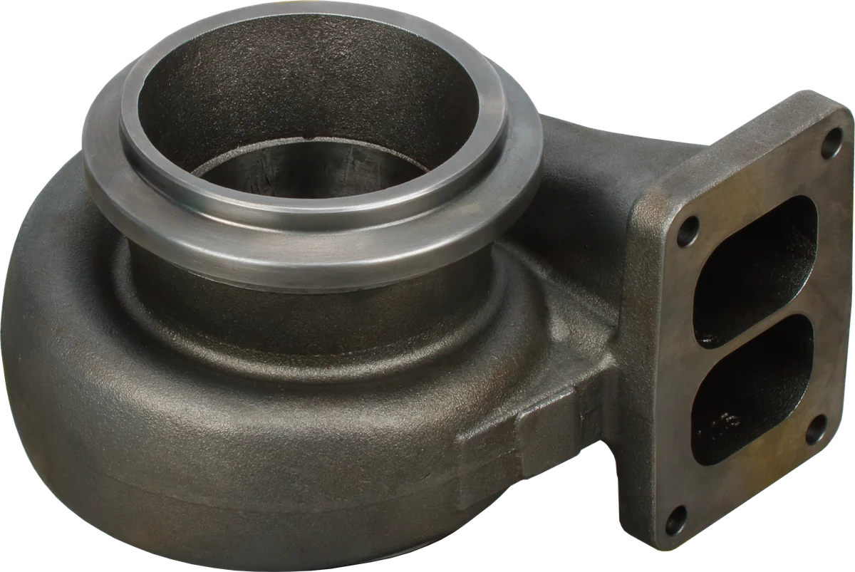
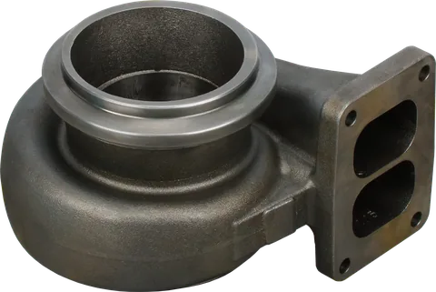
Exhaust inlet: verify the flange and passage geometry.
Turbine cavity: check clearance and contact damage.
Mounting face: the replacement must match the interfaces.
Product photograph from 2026. Numbers identify the features explained below.
How does manifold size affect turbocharger response?
When comparing small vs large turbo manifolds, consider how manifold cross-section, manifold runner length, and exhaust manifold volume work together. Changing pipe diameter changes both flow area and internal volume; adding length also adds volume and exposed surface. Looking at just the outlet diameter misses these combined effects.
| Design choice | Effect on turbine supply | Practical tradeoff |
|---|---|---|
| Smaller passage area | Can preserve a stronger pulse by keeping branch volume compact | Excessive restriction raises flow losses and cylinder pumping work. |
| Bigger passage area | Can reduce restriction where the original passage is undersized | Added volume can soften pressure pulses and delay pressure buildup. |
| Longer runners | Change when pressure waves and their reflections reach other junctions | Add surface area, volume, packaging demands, and potential heat loss. |
| Larger collector | Smooths pressure fluctuations before the turbine | Can sacrifice pulse strength; usefulness depends on duty and the turbine match. |
Pressure waves travel through the hot gas; their speed differs from the average gas velocity. Reflections from junctions and the turbine can help or hinder cylinder emptying depending on when they return. Engine speed and exhaust temperature change that timing. Equal-length runners alone therefore cannot guarantee a benefit across a diesel's operating range.
The turbine's effective flow area depends on its housing, wheel passages, and any nozzle or variable vanes. Too little area can raise upstream pressure and pumping losses; too much can weaken response at lower flow. A freer-flowing manifold cannot compensate for an unsuitable turbine selection or malfunctioning vane mechanism.
Group cylinders according to their exhaust events
The firing order is the starting point for cylinder grouping. A cylinder beginning its strong exhaust burst should not send a large pressure pulse toward another cylinder finishing exhaust, especially during valve overlap, when both intake and exhaust valves are open. High pressure at that second port can reduce scavenging or encourage reverse flow.
For fabrication, map the actual firing sequence onto the proposed branches. Include valve events when assessing interference, because equal firing intervals do not mean the exhaust valves are closed between pulses. Physical neighbors along a cylinder head are not automatically the right cylinders to connect.
If the engine uses separated pulse paths, preserve them through the collector, gasket, adapter, and divided turbine entrance. An open adapter or a divider that stops short can reconnect branches intended to remain separate. Confirm the arrangement for the specific engine before copying a visually similar manifold.
Where a pulse converter fits
A pulse converter uses shaped branch outlets and a mixing section to manage flow where exhaust streams join. A strong pulse accelerates through a nozzle-like passage, transferring momentum to gas in the common passage. Under suitable conditions, this ejector action can help draw flow from a quieter branch and reduce interference.
The device redistributes pressure and velocity; it does not create energy. Its restrictions and mixing also produce losses. The result depends on nozzle area, branch geometry, pulse timing, and the turbine downstream.
For repair work, preserve the original junction geometry. For a custom manifold, use analysis and operating measurements to establish whether a proposed nozzle and mixing section improve performance across the intended operating range. Simply adding a restriction at a junction can increase pumping losses.
Keep heat in while allowing the metal to move
Heat that escapes before the turbine reduces the energy available for expansion through it. Long exposed runners and unnecessary adapters add surfaces that shed heat. Restore specified heat shields and evaluate clearances around hoses, wiring, and bodywork.
Insulation changes the manifold's temperature as well as its surroundings. Wraps, blankets, and coatings can retain heat, but may increase metal temperature or alter temperature gradients. Use products approved for the component and duty; adding insulation without considering material limits and expansion can shorten service life.
A manifold grows as it heats. Uneven temperatures and restrained movement create stress; repeated cycles can turn that stress into cracks. Wrong studs, missing spacers, unsuitable gaskets, or an incorrect tightening procedure can change clamping and prevent intended movement. Include the surrounding installation in the failure investigation.
| Finding | Possible contributor | What to inspect |
|---|---|---|
| Crack beside a mounting ear | Restricted expansion or uneven clamping | Stud specification, spacers, washers, tightening sequence, and flange condition. |
| Repeated crack at the outlet | Turbo or exhaust pipe loads adding bending stress | Required supports, bracket alignment, and exhaust flexibility. |
| Crack around a runner junction | Local temperature differences, stress concentration, or fatigue | Casting condition, duty changes, and uneven cylinder operation. |
| Soot or fretting at a joint | Leakage, movement, or loss of clamp load | Correct gasket, mating surfaces, joint design, and hardware. |
Crack location helps direct inspection but cannot establish the cause alone. A replacement manifold can fail again if the mounting load or overheating condition remains.
Exhaust manifold checks before turbocharger replacement
Inspect the whole path upstream of the turbine while access is available. Escaping gas removes part of the flow and energy intended for the turbocharger. A leak can also distort the conclusions drawn from a low-boost complaint.
| Check | Shop action | Acceptance basis |
|---|---|---|
| Upstream leaks | Look for soot tracks, damaged joints, cracks, and loose plugs; use the approved leak-test procedure. | Sealed joints and no unresolved crack or leak. |
| Flange flatness | Clean the mating surfaces and check with a straightedge and feeler gauges as specified. | Engine or component manufacturer's limits. |
| Internal debris | Inspect every runner and collector for scale, casting sand, weld spatter, fragments, and loose internal pieces. | Clean, sound passages with no loose material. |
| Gaskets and dividers | Compare openings, orientation, and divider alignment before assembly. | Correct sealing without obstructing flow or connecting separated entries. |
| Fasteners and supports | Verify hardware, tightening procedure, expansion joints, and brackets. | Specified clamping and movement without forcing parts into position. |
Perform grinding, welding, and cleaning with the manifold removed and the engine ports protected. Remove any temporary plugs before assembly. Follow the manufacturer's repair limits for distortion; pulling a warped flange flat with bolt torque can overload the casting and fasteners.
Bring the turbo and exhaust connections into alignment without using their bolts to drag them together. After the prescribed initial run, check for leaks and interference. Retorque only if the service procedure requires it.
Judge aftermarket claims against the actual application
When comparing a turbo exhaust manifold with the original, ask for evidence at the engine speeds and loads you actually use. A claim of lower restriction does not establish better low-speed response, acceptable exhaust temperatures, or longer life.
Useful comparisons hold the turbocharger, fueling, calibration, and test conditions consistent. Evaluate load pickup, exhaust pressure and temperature at defined locations, and mounting durability. Surface appearance and outlet diameter reveal little about those results. For a straightforward replacement, prioritize correct geometry, material suitability, and provision for thermal movement.
Common Questions
Will a larger manifold make the turbocharger respond faster?
Only if it corrects a meaningful restriction. Added volume can weaken pulse delivery, so runner size must suit engine flow, operating speed, and turbine capacity.
Do diesel manifold runners need to be equal length?
Equal length can help control pulse arrival timing. Cylinder grouping, collector geometry, heat loss, and the intended speed range also determine whether it helps.
Is wrapping a cast manifold a good upgrade?
Use insulation approved for the manifold and duty. Retained heat can increase metal temperature and change thermal stresses. Restore specified shields and follow component guidance.
Can cracked manifolds damage a replacement turbocharger?
A crack can leak exhaust energy; loose internal fragments may strike the turbine wheel. Inspect the passages and resolve the cracking cause before installing the replacement.
Should manifold bolts be tightened again after warmup?
Follow the specified service procedure. Some assemblies require a recheck; others do not. Extra tightening can damage fasteners or interfere with the intended expansion arrangement.
What should I check before choosing a turbo exhaust manifold?
Confirm engine identification, turbocharger part number, ports, flanges, cylinder grouping, supports, and required connections. Consider the duty cycle and any history of repeat cracking.
What are the symptoms of a turbocharger exhaust manifold leak?
Soot tracks or fretting at manifold joints can indicate a leak. Escaping exhaust gas reduces the flow and energy reaching the turbocharger and can complicate low-boost diagnosis. Check for damaged joints, cracks, and loose plugs, then follow the approved leak-test procedure.
For help identifying the right replacement turbocharger, contact LeadTurbo with the turbo part number, engine details, and application.