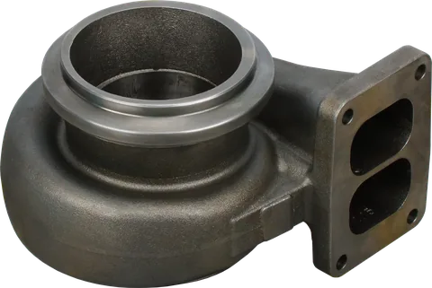
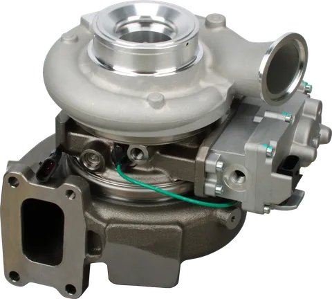
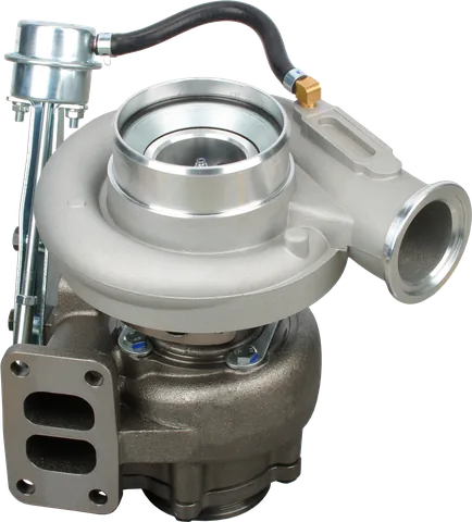
Seeing an extra turbine housing on a diesel does not tell you whether the engine has another compression stage or a device that adds crankshaft power. That distinction matters when a truck has low power with normal turbocharger boost.
Before diagnosing or ordering parts, identify the air path, exhaust path, and mechanical or electrical connections. Similar names can describe very different hardware.
Turbocharger vs power turbine: air supply and power recovery
An ordinary turbocharger already uses exhaust energy to drive its compressor. A recovery arrangement goes further by making turbine output available for another useful job, such as helping turn the crankshaft.
In engineering usage, compound charging means a turbocharger combined with a mechanically driven supercharger. In North American diesel shops, "compound turbos" usually means two turbochargers in series. Neither is turbocompounding, which exports exhaust energy as shaft or electrical power, so confirm the actual layout before relying on a label.
| System | What it does | Identifying feature |
|---|---|---|
| Turbo plus supercharger, series | Compresses the same intake stream in successive devices | Air passes through both compressors |
| Turbo plus supercharger, parallel | Adds air from separate branches | Branches feed a common intake |
| Mechanically interconnected system | Shares power between turbo machinery and crankshaft | Gears and a suitable coupling or clutch |
| Separate power turbine | Extracts work beyond the boost turbine | Exhaust turbine connected to a recovery driveline |
| Electrical recovery | Converts turbine work into electricity | Generator and power electronics |
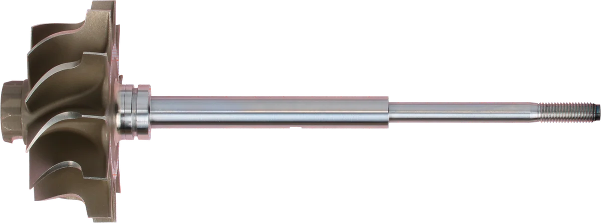
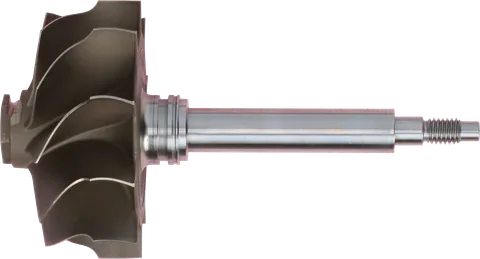
Turbine wheel: exhaust energy drives the shaft.
Shaft surface: inspect wear and scoring before reuse.
Shaft end: connects to the compressor-side rotating parts.
Product photograph from 2026. Numbers identify the features explained below.
How turbocompounding recovers useful work
In a typical heavy truck recovery layout, exhaust first passes through the turbocharger turbine that drives the intake compressor. It then flows through a separate power turbine before continuing toward the exhaust outlet. That second turbine has no intake compressor to drive.
Its shaft instead delivers torque through reduction gearing to the engine. Where fitted, a fluid coupling transfers torque while allowing a speed difference and cushioning torsional disturbances from combustion. It is part of the power transmission system, alongside the reduction gears.
A turbo compound diesel engine can therefore deliver some of its output through a route that bypasses the pistons. However, the added turbine also creates exhaust resistance. The engine must push gases against that pressure, increasing pumping work.
The useful result is recovered output after extra pumping work and transmission losses are accounted for. More turbine loading is not automatically better. Turbine sizing, control strategy, and engine operating conditions determine whether the complete system gains efficiency.
When power can flow in both directions
A different arrangement mechanically connects the turbocharger shaft to the crankshaft. Depending on the design, the connection can support the compressor when the exhaust turbine cannot supply enough power, then return surplus turbine output when conditions allow.
| Operating condition | Possible power flow | Practical meaning |
|---|---|---|
| Low exhaust power | Crankshaft assists the compressor through the transmission | Boost support consumes engine output |
| Near a power balance | Assistance falls away; some designs disengage the drive | The compressor can run on turbine power |
| Surplus turbine power | Excess turbine output passes through gearing toward the crankshaft | Recovered energy contributes to useful output |
The transition depends on torque demand, shaft speed, and the actual clutch or coupling arrangement; it does not occur at one universal engine speed. Not every installation can disengage, and not every geared recovery system provides assistance at low load.
This distinction prevents a common diagnostic mistake: expecting a separate truck power turbine to behave like a compressor assisted by the crankshaft. Check the manufacturer’s description of power flow before deciding that a clutch, gearset, or coupling has failed.
How series and parallel compound charging differ
In a series layout, intake air passes through both the turbo compressor and a mechanical supercharger, so their pressure ratios multiply; in a parallel layout, separate branches feed a common intake and check valves stop air escaping backward through the weaker branch. The mechanical stage keeps air flowing when exhaust energy is weak, which matters most on engines that need a pressure difference for scavenging. Either way, compound charging only moves air: it does not return exhaust energy to the crankshaft.
Electrical exhaust energy recovery
A turbine can drive a generator instead of a gear train. The electricity can supply vehicle loads, support an electric drive, or charge energy storage when the installation includes it.
The generator may share the main turbo shaft or use a separate exhaust turbine. Either way, useful output must exceed the added pumping and conversion losses. Generating electricity loads the turbine; it does not make exhaust restriction disappear.
Keep recovery separate from electric assistance when reading a wiring diagram. A motor that speeds up a compressor is an energy consumer during that operation, even if the same machine can generate in another mode.
Very high boost with an auxiliary combustion chamber
A rare, mostly experimental or military arrangement, which you will not meet on trucks or farm equipment, adds a small combustion chamber ahead of the turbine. Part of the compressed air goes into the engine, while another part bypasses the cylinders and supports combustion in this chamber. The resulting hot gas supplies additional turbine power.
In plain words, the system can burn extra fuel outside the cylinders to keep its air supply strong when engine exhaust alone is inadequate. Starting equipment first establishes the necessary airflow; ignition and fuel controls then manage the auxiliary flame.
This arrangement can support an engine designed around high boost and a lower geometric compression ratio. Lower compression can make starting harder, which helps explain the need for independent boost support.
Every gram of fuel burned in that chamber counts against overall economy. High boost does not automatically leave cylinder pressure, component temperatures, or emissions unchanged; those depend on the complete engine design.
Match expectations to the duty cycle
The value of turbocompounding depends on how often the engine produces enough exhaust flow and energy to offset recovery losses. Sustained highway pulling or a steadily loaded industrial installation can offer favorable conditions. At the same required shaft output, successful recovery can reduce engine fuel consumption.
Equipment that spends much of its day idling may see far less benefit. At light load, extra restriction, bearing friction, gear losses, and coupling losses can consume the small amount recovered. Bypass or disengagement strategies can reduce that penalty where provided.
Evaluate the application using these checkpoints:
- Time under substantial load matters more than a peak horsepower claim.
- Compare fuel use at equivalent delivered work and comparable operating conditions.
- Include the auxiliary chamber’s fuel or electrical system’s losses where applicable.
- Account for extra weight, cooling demand, maintenance, and downtime.
Service the complete power path
Normal boost does not prove the recovery system is healthy. The compressor may still meet its target while a separate turbine, coupling, or generator fails to deliver useful power. Conversely, an engine control fault can limit recovery without any broken rotating hardware.
| Symptom | Possible area to investigate | Useful next check |
|---|---|---|
| Weak pulling with plausible boost | Recovery torque transfer or control limitation | Compare commanded and measured recovery data, if available |
| New whine or gear noise | Reduction gears, bearings, or another engine accessory | Localize the noise using the approved procedure |
| Unexpected coupling temperature | Excessive slip, lubrication, or cooling problem | Check specified fluid condition, supply, and operating limits |
| High exhaust restriction | Recovery turbine, bypass hardware, or other exhaust components | Measure pressure at the prescribed test points |
| Low electrical recovery | Generator, power electronics, wiring, or control strategy | Follow diagnostic codes and specified electrical tests |
These are diagnostic directions, not proof that the listed part has failed. Follow the engine-specific test sequence and establish whether the complaint occurs hot, cold, during acceleration, or at steady load.
Before removing parts:
- Identify each assembly separately: boost turbocharger, power turbine, drive unit, coupling, and any generator.
- Check the specified lubrication paths. Shared oil systems can spread wear debris beyond the failed unit.
- Inspect gears, drive connections, and coupling condition using the manufacturer’s wear limits; avoid generic play limits.
- Preserve timing, alignment, and calibration requirements when separating the recovery drive.
- Use the required electrical isolation procedure before working on generator or power electronics connections.
Do not assume every coupling shares the engine’s oil supply or uses the same service procedure. Verify its lubrication arrangement before draining, filling, or flushing anything. If debris is present, inspect the connected circuit and determine the approved cleaning scope before installing a replacement.
Gear tooth wear, bearing damage, and fluid coupling deterioration can reduce recovery and create secondary damage. A replacement CHRA addresses the turbocharger’s rotating center assembly; it does not repair a worn recovery gear train. Treat each serviceable unit according to its own parts specification.
Common Questions
Is compound turbocharging the same as energy recovery?
No. In shop language, compound turbos usually means two turbochargers compressing intake air in stages, and in engineering usage compound charging means a turbo plus a mechanical supercharger. Neither arrangement exports power to the crankshaft or an electrical load; turbocompounding does.
Can the crankshaft help drive the turbocharger?
Yes, in a design with a suitable mechanical connection. The crankshaft can supply missing compressor power when exhaust energy is insufficient. Separate recovery turbines do not automatically provide this assistance.
Does electrical boost always recover exhaust energy?
No. An electric compressor can consume battery or alternator power without recovering exhaust energy. Recovery requires an exhaust turbine driving a generator that supplies useful electrical power.
Can a turbocharger replace a power turbine?
No. The power turbine serves a different purpose from a conventional turbocharger and connects to a recovery driveline or generator. Replacement parts must match the specific assembly and engine configuration.
Where does turbocompounding deliver the most value?
Its strongest case is sustained operation at substantial load. Compare fuel savings over the actual duty cycle with added maintenance, repair costs, and downtime.
How does turbocharger energy recovery work?
Turbocompounding recovers exhaust energy as shaft or electrical power. Turbine output can help turn the crankshaft through a mechanical connection or drive a generator supplying useful electrical power.
For help identifying the right replacement turbocharger, CHRA, or turbo parts, contact us with the part number and engine details.