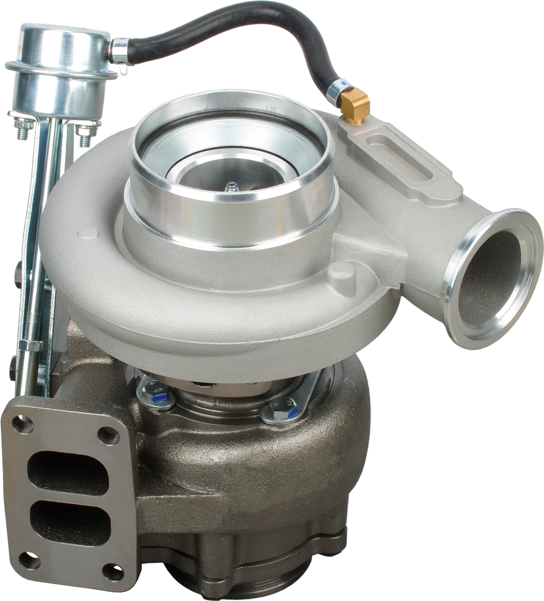
Low boost, a hiss under load or a coupling that keeps blowing off can start with a small installation fault. Before condemning the turbocharger, inspect the path between its outlet, the charge-air cooler and the intake manifold. A dependable repair requires compatible hose material, suitable clamps and pipework that stays aligned without trapping normal engine movement.
Recognize diesel turbocharger boost leak symptoms before replacing parts
Leaks often become obvious during acceleration or sustained work, when pressure and airflow rise. An engine that sounds normal at idle can still lose charge air while pulling a trailer, climbing a grade or driving a hydraulic load.
| Symptom | What it suggests | What to check |
|---|---|---|
| Low boost or slow response | Escaping air is one possibility | Loose connections, hose splits and displaced couplings |
| Hiss or rushing noise under load | A leak opening under pressure | Hose undersides, bends and sealing areas |
| Black smoke with reduced power | Too little usable air for the fuel delivered | Charge plumbing alongside other intake and engine checks |
| Oil-and-dust ring near a joint | Residue may be escaping at the seal | Clean the area, inspect the joint and confirm leakage |
None of these proves a turbo boost leak. Control faults, restrictions and other engine problems can produce similar symptoms. A diesel particulate filter can also prevent visible black smoke, so a clean-looking exhaust does not rule out lost charge air.
Why connections fail under load
A coupling has to contain pressure while tolerating changing temperature and relative movement. Several stresses commonly act together, which helps explain why turbocharger hoses blow off:
- Pressure: Internal pressure loads the hose wall and pushes connected sections apart. For the same pressure, a larger pipe diameter creates greater separating force.
- Heat cycling: Repeated warming and cooling change joint dimensions. Hose material also relaxes under compression, which can reduce the grip of a rigid clamp.
- Vibration: Unsupported pipes shake against couplings, brackets and nearby hardware. Small repeated movements can wear through an otherwise sound hose.
- Engine movement: The engine shifts on its mounts while the cooler may be attached to the chassis. A short, stretched connector absorbs that difference poorly.
- Oil exposure: Mist from crankcase ventilation can reach the charge tract. An unsuitable hose compound may soften or swell, while oil on sealing surfaces can encourage slipping.
The turbocharger outlet also exposes its coupling to hotter air than a connection after the cooler. Choose parts for their installed location and service conditions.
A hose that repeatedly separates also deserves a check of actual operating boost against the engine’s specification. Repairing the joint does not resolve a pressure-control fault. Do not fit a stronger clamp as the sole response to unexpected overboost.
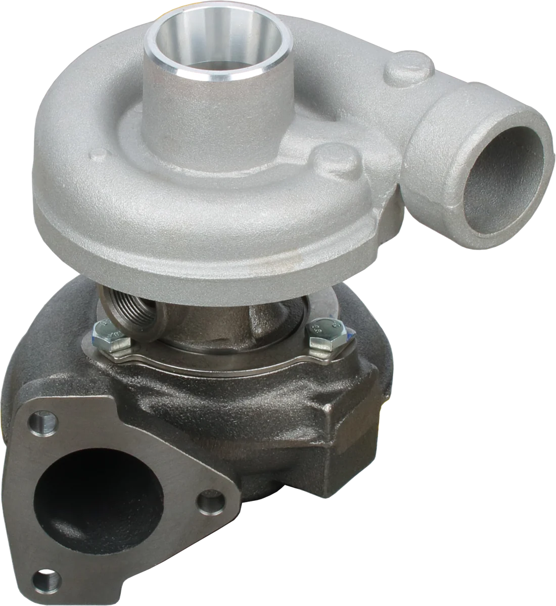
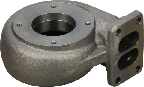
Compressor housing: guides the compressed air.
Turbine housing: guides exhaust gas to the turbine.
Actuator: check its type, linkage and calibration.
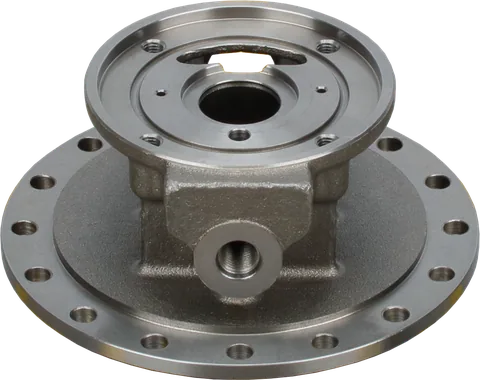
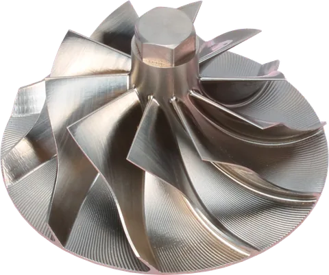
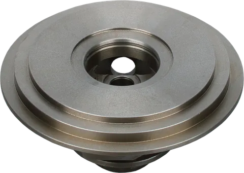
Product photograph from 2026. Numbers identify the features explained below.
How to choose a turbocharger boost hose
When comparing silicone vs rubber turbocharger hoses, material names are only a starting point. Check the complete hose’s pressure rating at the expected operating temperature, its oil compatibility and its intended application. A coolant hose is not a suitable substitute simply because the diameter matches.
| Hose type | Useful characteristics | Main selection caution |
|---|---|---|
| Application-rated rubber | Can provide the specified flexibility and durability in an original equipment installation | Rubber compounds differ; confirm charge-air, temperature and oil ratings rather than assuming all black hose is equivalent. |
| Reinforced silicone | A silicone intercooler hose combines a flexible elastomer with fabric layers that carry pressure loads | Ordinary silicone is not automatically suitable for prolonged oil exposure; inspect the actual specification. |
| Fluorosilicone-lined reinforced silicone | An inner liner improves resistance to oily charge air while the reinforcement provides strength | The liner does not make every hose suitable for every fluid, pressure or temperature. |
Fabric type, layer design and manufacturing quality all affect performance. Ply count alone does not establish a safe working pressure. Inspect the liner as well as the outside: internal separation can exist beneath a cover that looks acceptable.
Match the shape of a replacement turbocharger boost hose, too. Molded elbows avoid forcing straight hose around a corner. A purpose-designed hump or bellows coupling can accommodate specified movement, but it cannot correct badly positioned pipes or failed mounts.
Compare clamps by how they maintain grip
A T-bolt clamp can provide substantial clamping force, but a rigid version does not automatically compensate for dimensional changes. Constant-tension designs use a spring element to help preserve clamping load as the joint changes size. They still need the correct diameter range and installation setting.
| Clamp type | How it behaves | Service considerations |
|---|---|---|
| Conventional worm-drive | Screw adjustment tightens the band without active spring compensation | Use only an appropriate specified design; narrow or exposed perforated bands can damage soft hose. |
| Rigid T-bolt | A bolt draws a broad band around the joint | Size it correctly; excessive tightening can harm the hose or deform a thin pipe. |
| Spring-loaded T-bolt or constant-tension worm-drive | A spring mechanism allows limited adjustment as dimensions change | Follow the specified torque or spring setting; do not assume more spring compression is better. |
| Spring-band | The band itself acts as the spring | Use the correct application-rated size and installation tool; suitability for charge air must be confirmed. |
Constant tension means controlled compensation within a working range, not unlimited self-adjustment. It cannot repair a split hose or retain a poorly assembled joint. A smooth inner surface or protective liner can help prevent band edges and slots from damaging the cover.
Select the turbocharger hose clamp size from the assembled hose outside diameter, accounting for the pipe and wall thickness. A clamp labeled for a similar nominal hose size may still have the wrong adjustment range.
How should a boost hose and clamps fit together?
Start with the correct hose bore for the pipe’s outside diameter. An oversized coupling tightened into folds will not produce dependable contact. A reducer belongs where pipe sizes change; a clamp cannot replace one.
- Check the pipe bead. On a conventional beaded connection, the raised ring helps resist hose pull-off. A missing, crushed or damaged bead needs correction according to the pipe specification.
- Position the clamp behind the bead. Place the band on supported hose toward the pipe body, away from the open pipe end, at the specified setback. Do not center it over the bead.
- Confirm insertion depth. Follow the seating marks or assembly dimensions. The hose must overlap enough supported pipe for the entire band, while preserving any specified gap between pipe ends.
- Align without preload. The coupling should not be twisted, kinked or stretched into position. Allow the intended flexible section to move rather than using its full travel just to connect the pipes.
- Restore the supports. Check brackets, isolators and engine mounts. Support each pipe at its intended points without rigidly bridging components that need to move relative to each other.
Reference marks across the hose and pipe can reveal later movement. Keep them clear of the sealing area, and verify that clamp hardware cannot rub neighboring hoses or wiring.
Use the specified tightening method
Get the instructions for the actual clamp and hose assembly. Torque depends on band design, fastener size, thread condition and the manufacturer’s intended installation. There is no universal value for all boost couplings, and engine boost pressure is not a torque setting.
Clean mating surfaces and remove oil using a method compatible with the hose. Do not add lubricant or sealant unless the installation procedure calls for it. Assemble squarely, tighten with the specified tool and use a suitable torque wrench where torque is prescribed.
Stop if the band distorts, the hose extrudes or the fastener reaches its travel limit before seating correctly. Extra tightening may damage reinforcement or distort the pipe. Perform any required follow-up check under the specified temperature conditions; do not improvise a hot retorque.
Inspect before returning the engine to work
Work with the engine stopped, components cool and trapped pressure released. Inspect the complete route, including hidden surfaces close to brackets and heat sources.
- Look for cuts, rubbing, hardening, swelling, blisters and exposed reinforcement. Compare suspect areas with undamaged portions of the hose.
- Remove suspect couplings to inspect their inner surfaces for tears or separation. Replace damaged hose rather than covering the defect.
- Inspect pipe ends for cracks, corrosion, dents and damaged beads. Confirm that sealing areas are clean and round.
- Check bands, screws, nuts and springs for corrosion, distortion or damaged threads. Verify that the clamp is within its usable diameter range.
- Look for shifted witness marks, fresh residue and contact with nearby parts. Confirm bracket fasteners and isolators are serviceable.
- Check clearances through the movement allowed by the installation. Replacing a hose alone will not cure repeated rubbing or excessive engine movement.
Confirm the repair with the manufacturer’s leak-check procedure, using regulated pressure and secured adapters within the specified test limit. Keep people clear of pressurized plugs and couplings. Then verify operation under appropriate load and inspect again as instructed. If symptoms remain, continue diagnosis rather than assuming the turbocharger needs replacement.
Common Questions
Is silicone always better than rubber?
No. An application-rated rubber hose can be the correct service part. Reinforced silicone is useful when its temperature and pressure ratings suit the location, but oil compatibility still needs checking. Match the engine specification rather than choosing by material name alone.
Does a T-bolt clamp automatically maintain tension?
No. A rigid T-bolt clamp provides clamping force without automatic spring compensation. A spring-loaded version can accommodate some dimensional change, provided it is correctly sized and installed within its specified working range.
Will tightening the clamp stop a hose blowing off?
Only if insufficient clamping was the cause and the parts remain serviceable. Repeated blow-offs call for checking pipe retention features, insertion depth, hose size, alignment, mounts and pressure control. More tightening can damage the hose or pipe.
Does oil around a coupling mean the turbocharger has failed?
No. Oil mist from the crankcase ventilation system can leave residue at a leaking joint. Heavy wetting, pooling or rising oil consumption needs investigation, but an oily coupling alone does not identify the failed component.
Can I reuse a boost hose and clamps after a blow-off?
Reuse them only if the service instructions permit it and inspection finds no damage or distortion. Replace hoses with torn reinforcement, damaged liners or permanent stretching, and clamps with damaged bands, threads or springs. Correct the reason for separation before returning the engine to load.
How tight should turbo hose clamps be?
Follow the instructions for the actual clamp and hose assembly. There is no universal torque value, and engine boost pressure is not a torque setting.
For help identifying replacement turbocharger parts, contact us with the part number, engine model and equipment details.