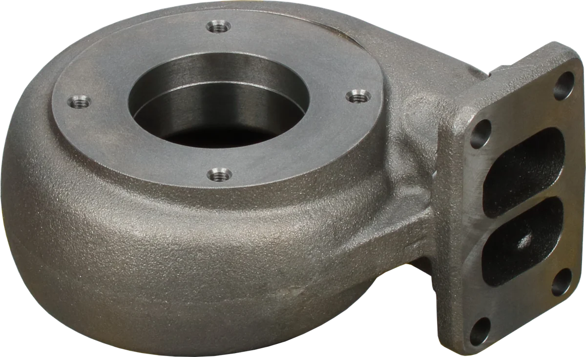
Choosing an "EGT gauge diesel" kit starts with probe location and the engine specification used to interpret its readings. A loaded pickup, excavator, and generator each need operating references that match the engine and measurement point.
Why EGT is a key diesel safety reading
Exhaust gas temperature tracks heat leaving combustion and entering the exhaust system. Diesels usually operate with excess air; under substantial load, adding fuel relative to the available air commonly raises exhaust temperature. EGT therefore reflects the relationship between air supply, fueling, and thermal load.
An exhaust temperature rise can appear before the coolant gauge shows much change. Watching that trend gives an operator time to reduce demand before prolonged heat damages exhaust components or the turbocharger. Both temperature and exposure time matter.
However, EGT does not directly measure air-fuel ratio or piston, valve, or turbine metal temperature. Injection timing, intake temperature, and engine controls also affect it. Use EGT alongside oil pressure and coolant temperature, with limits tied to the specific engine.
Obtain the continuous limit and any permitted short-duration excursion for your engine configuration. Confirm whether the specification refers to the manifold, turbine inlet, or another location. A momentary peak and a long uphill pull impose different heat exposure. Apply any short-duration allowance only as documented by the manufacturer. Factory protection and derate functions should remain active.
How to measure turbocharger exhaust temperature
A diesel pyrometer typically uses a thermocouple: two different metal alloys form a sensing junction, producing a small electrical signal related to temperature. The instrument interprets that signal with compensation for temperature at its reference connection. Type K probes are common, but the probe and display must be compatible.
The tip samples local exhaust gas. A tip against the passage wall can read differently from one correctly exposed to the flow. Follow the specified insertion depth.
| Item | What to verify |
|---|---|
| Sensor and display | Matching thermocouple type, supported junction design, and correct polarity |
| Temperature rating | Suitable continuous service rating for the intended exhaust location |
| Leads and connectors | Compatible thermocouple extension materials and permitted connection methods |
| Mounting hardware | Specified thread, insertion depth, retention, and exhaust sealing |
| Warning functions | Adjustable alerts and an identifiable sensor-fault indication |
Do not replace thermocouple extension cable with ordinary copper wire unless the instrument manufacturer specifically allows it at that connection. Incorrect alloys, reversed polarity, loose terminals, or electrical interference can create misleading readings without a mechanical engine problem.
Probe construction affects response time. A protective sheath helps durability but can delay response to a rapid temperature change. Use an exhaust-rated assembly with appropriate vibration resistance; the display may lag the event.
When choosing an EGT gauge for a diesel turbocharger, select a display range that covers the documented operating range without making useful changes difficult to see. A stored peak can help a technician review a run, but it does not show how long the engine spent at that temperature.
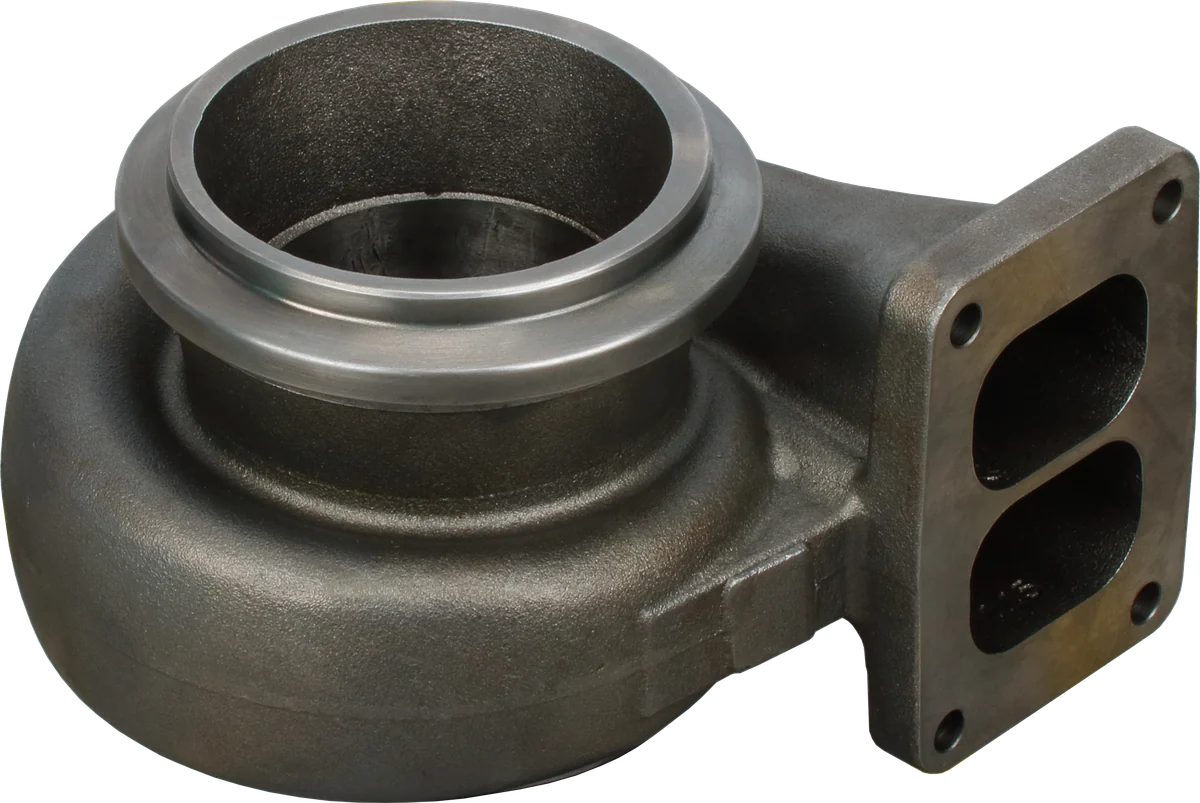
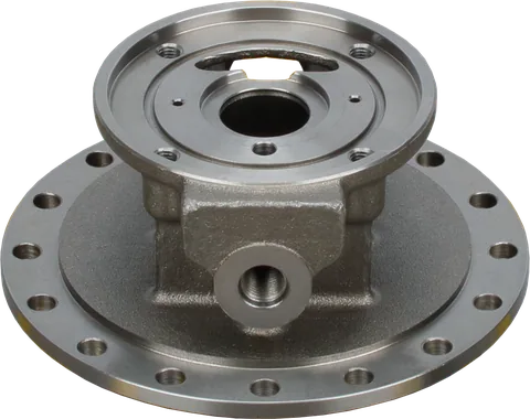
Exhaust inlet: verify the flange and passage geometry.
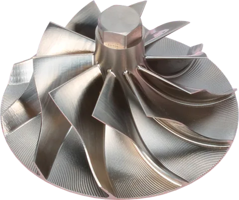
Turbine cavity: check clearance and contact damage.
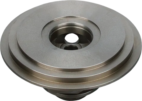
Mounting face: the replacement must match the interfaces.
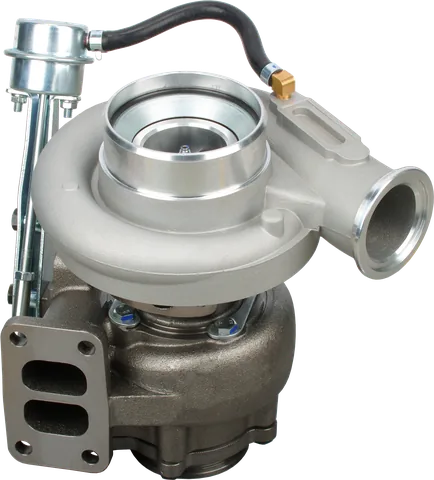
Product photograph from 2026. Numbers identify the features explained below.
EGT probe before or after the turbocharger?
Before setting an alarm, decide whether you need pre-turbo EGT or post-turbo EGT. A temperature limit is meaningful only when it applies to the same measurement position.
| Probe position | What it represents | Main consideration |
|---|---|---|
| Manifold collector before turbine | Combined exhaust from the cylinders feeding that passage | Useful for inlet-temperature monitoring; installation must protect the turbine from debris |
| Individual manifold runner | A local cylinder or branch reading | May miss a hotter cylinder elsewhere; follow the engine-specific monitoring arrangement |
| Turbine outlet or downpipe | Gas after turbine expansion | Requires outlet-specific reference values; distance downstream affects the measurement |
The turbine extracts energy as exhaust expands through it, turning the shaft that drives the compressor. That work generally leaves the gas cooler at the outlet. Heat loss through surrounding metal and downstream piping also influences readings.
For illustration, comparing turbocharger inlet vs outlet temperature on a loaded engine might reveal a difference of roughly 200–300°F (110–170°C). Actual differences can fall outside that range and change with exhaust flow, turbine operating conditions, and load. A fixed addition cannot reliably turn an outlet reading into an inlet safety limit.
On engines with multiple turbochargers, identify which turbine the probe precedes or follows. Sensors around aftertreatment equipment may reflect regeneration heat and are not automatically equivalent to either location.
Install the probe without risking the turbine
An upstream installation can expose the turbine to machining debris or a broken probe tip. Either can damage the turbine wheel. Cleanliness and mechanical retention are essential.
- Use an approved, already-machined port where available. Do not drill a turbine housing unless the manufacturer provides a procedure for that location.
- When drilling or tapping is necessary, remove the manifold or exhaust section. Deburr, thoroughly clean, and inspect the passage before reassembly.
- Do not depend on grease, a magnet, vacuum suction, or a running engine to keep every chip away from the turbine.
- Fit the probe with the specified engagement, insertion depth, and torque. Ensure its tip cannot contact an internal surface.
- Route leads away from exhaust heat, sharp edges, and moving parts. Provide strain relief and use the specified extension wire.
- Check for exhaust leaks and a plausible cold reading. Verify the display responds during controlled warm-up before returning to loaded service.
Overheating, vibration, and unsuitable construction can weaken a probe tip. Use an exhaust-rated probe and inspect it during scheduled service. If a removed probe has a missing tip, keep the engine out of service and inspect the turbocharger for possible debris damage before restarting.
EGT gauge diesel: Reading temperature with boost
Pair the pyrometer with a boost gauge measuring intake-manifold pressure after the charge-air cooler. Compare both at similar RPM and demand. Higher EGT with lower-than-usual boost can suggest reduced air delivery, but the pair does not identify a failed component by itself.
Boost indicates pressure; the air mass available also depends on temperature and other operating conditions. Hotter intake air and changes in combustion can alter EGT while the pressure reading remains familiar.
On gasoline engines, wideband oxygen monitoring supplies mixture information that EGT cannot provide. Gasoline mixture targets do not belong in diesel gauge interpretation.
General guidance only: these patterns are not temperature limits for every engine. Use specifications for the actual probe location.
| Observed readings | What they suggest | Operator action |
|---|---|---|
| EGT settles at its established baseline; boost is familiar | Stable behavior for those conditions | Continue monitoring, provided readings remain within approved limits |
| EGT keeps climbing at steady demand | Increasing thermal load or a changed operating condition | Back off and watch whether temperature falls |
| EGT rises while boost falls below its usual level | Possible reduction in air delivery | Reduce load, then inspect the intake and charge-air path |
| EGT rises while boost looks normal | Pressure alone does not explain the heat | Reduce demand and review operating conditions and engine data |
| EGT approaches the applicable continuous limit | Remaining operating margin is shrinking | Reduce load before crossing the limit; follow engine instructions |
| EGT jumps, drops out, or becomes implausible | Possible sensor or wiring fault | Unload safely and verify the signal before relying on it |
Back off the throttle or reduce equipment load when EGT climbs unexpectedly. On a grade, an appropriate downshift may reduce lugging, provided RPM stays within the engine's operating range. On a generator, shed load according to its operating procedure. Watch for a clear temperature response.
Once safely unloaded, check the air filter restriction indicator, intake ducting, charge-air hoses, clamps, and cooler connections. Review engine warnings and fault codes. If excessive temperature persists, stop work safely and follow shutdown instructions. Our high EGT causes guide covers the broader diagnostic investigation.
Build a baseline your operators can use
After installation, record a healthy engine under repeatable conditions. Log probe position, units, RPM, load or gear, ambient conditions, boost, and stabilized EGT. Identify readings from one bank or cylinder, because they may not represent the hottest cylinder.
For example, compare the same pickup towing the same trailer on the same grade at a similar road speed. If EGT now rises faster and boost is lower, reduce demand and investigate before repeating the pull. If gear, outside temperature, or cargo weight changed, record that difference before deciding the turbocharger has deteriorated.
For fleet equipment, a log of the normal range during a repeatable task is more useful than a single remembered peak. Have the shop document the warning setting and the action the operator should take when it activates.
Keep these checkpoints with the machine:
- Use engine-specific continuous and short-duration limits for the actual probe location.
- Set warnings according to manufacturer guidance, allowing for sensor response and operator reaction.
- Compare trends under similar conditions; a hill, altitude change, or regeneration event can change the comparison.
Confirm that every operator knows whether the display uses Fahrenheit or Celsius and whether it reads before or after the turbine. A gauge's printed red zone is not an approved engine limit.
Common Questions
What EGT is safe for continuous diesel operation?
Use the engine maker's limit for the specified probe location and duty cycle. Continuous and brief excursion limits may differ. Another engine's limit is not a reliable reference for yours.
Is pre-turbo or post-turbo placement better?
Pre-turbo placement generally serves monitoring of turbine inlet heat. Post-turbo placement is useful when the application specifies it. Choose the location that matches your engine's available limits and installation instructions.
Can I calculate pre-turbo EGT from a post-turbo gauge?
A fixed correction is unreliable because turbine work and operating conditions change the temperature difference. Use an outlet-specific limit or an approved inlet probe when inlet temperature is required.
Does normal boost mean exhaust temperature is safe?
No. Boost indicates pressure, while EGT reflects exhaust heat. Charge temperature, fueling, and combustion conditions can change EGT without an obvious boost change. Watch both.
Can an existing factory exhaust sensor replace a pyrometer?
Only if its location and displayed data meet the monitoring requirement. An aftertreatment sensor may report regeneration temperatures rather than turbine inlet conditions. Confirm what the data channel represents.
What should an "EGT gauge diesel" kit include?
Choose a compatible display and exhaust-rated thermocouple, matching wiring and connectors, suitable mounting hardware, and clear instructions. Verify the kit supports your intended location and can display the engine's operating temperature range.
Which turbocharger EGT probe should I buy?
Choose an exhaust-rated probe matched to the display and intended measurement location.
Why is my turbo EGT gauge erratic?
Incorrect alloys, reversed polarity, loose terminals, or electrical interference can create misleading readings.
Contact LeadTurbo with your turbocharger part number and engine details for help identifying the correct replacement turbocharger, CHRA, or repair parts.