1. Plan how to rebuild a turbocharger
For serviceable journal-bearing units, this workflow covers how to rebuild a diesel turbocharger. Ball-bearing cartridges and variable-geometry hardware may require different equipment, procedures, or replacement assemblies. Obtain instructions and limits for the exact turbo part number before opening the rotating assembly.
With the engine cold and disabled, inspect shaft movement, blade condition, and visible housing damage. Some dry radial movement can be normal; finger feel cannot establish an acceptable clearance. Rubbing, chipped blades, binding, or obvious axial movement require measurement and investigation.
| Condition after inspection | Repair route to consider | Reason |
|---|---|---|
| Reusable shaft, wheels, and center housing | CHRA rebuild using the correct kit | Economical when measurement, balancing, and labor costs remain reasonable |
| Failed rotating parts; serviceable end housings | Matched replacement CHRA | Replaces the center housing and rotating assembly while retaining sound external housings |
| Unacceptable housing cracks or distortion, extensive damage, or unavailable service data | Complete turbocharger | Avoids rebuilding around uncertain parts or incompatible components |
When weighing a turbocharger rebuild vs replacement, compare total costs, including cleaning, inspection, damaged fasteners, balancing, calibration, and downtime. For a working truck or generator, the cheapest kit may produce the most expensive repair. Identify the original failure cause before returning any replacement to service.
2. Prepare a clean bench and specification sheet
Separate dirty disassembly from clean assembly. Use labeled trays, lint-free wipes, good lighting, and caps for exposed engine connections. Photograph hose routing, mounting positions, and actuator arrangements before removal; support heavy housings independently.
Have the tools needed to rebuild a turbocharger and supporting service information ready:
- Low-range torque wrench, angle gauge if specified, correct sockets, and the designated shaft-holding fixture.
- Micrometers, a suitable bore gauge, dial indicator, and the prescribed runout fixture.
- Correct snap-ring pliers, nonmarring handling tools, and a compatible parts-cleaning system.
- Service limits, tightening procedures, parts diagram, and a balancing shop willing to accept the job.
Record required journal diameters, bore sizes, shaft runout, ring clearances, end play, and radial measurement method. Calipers alone cannot qualify bearing fits. Arrange balancing before buying parts.
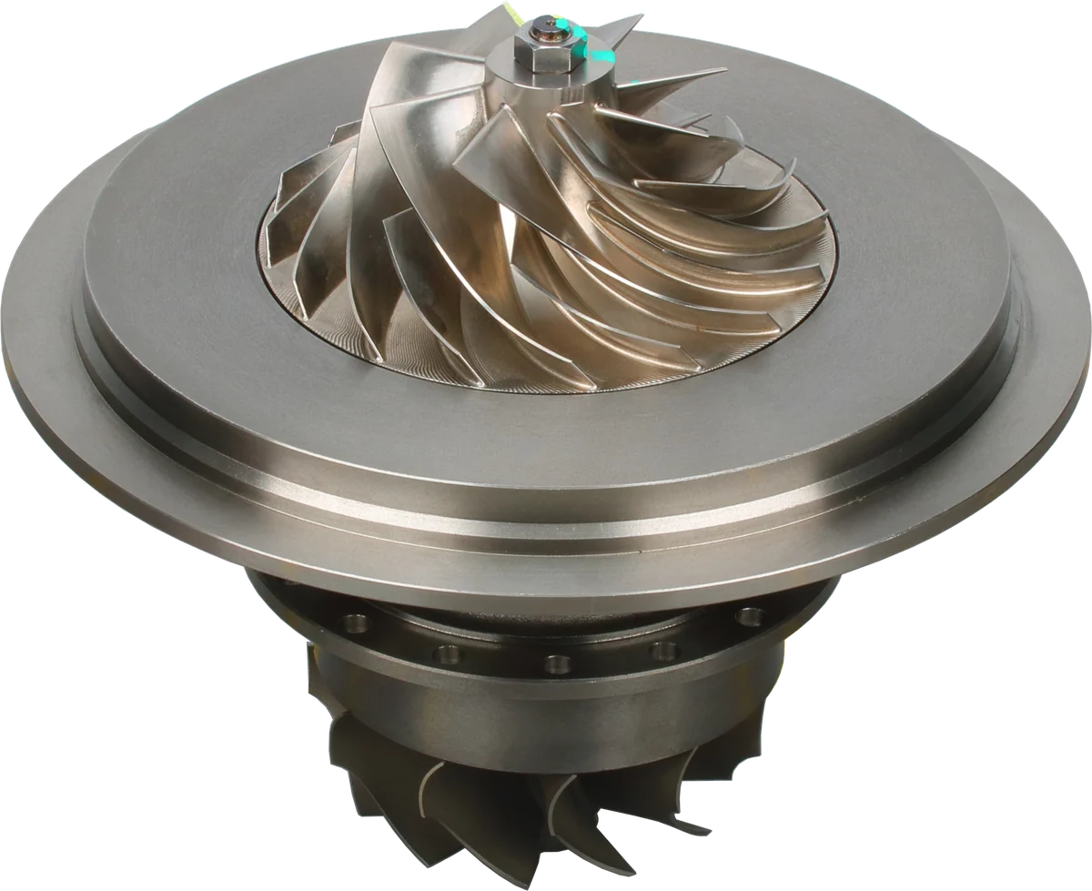
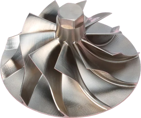
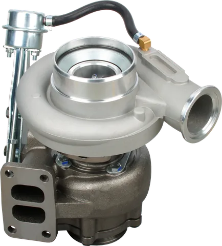
Compressor wheel: transfers shaft power to the air.
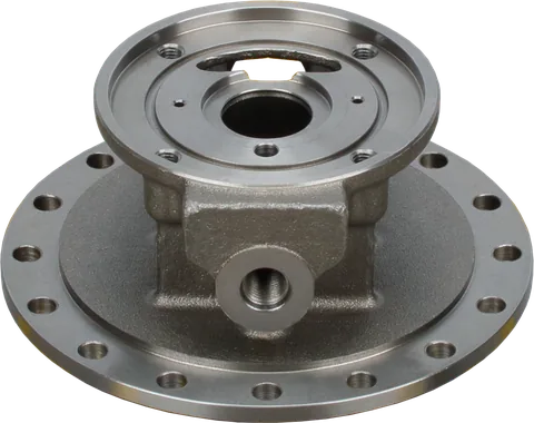
Bearing housing: supports the lubricated rotating assembly.
Turbine wheel: exhaust energy drives the shaft.
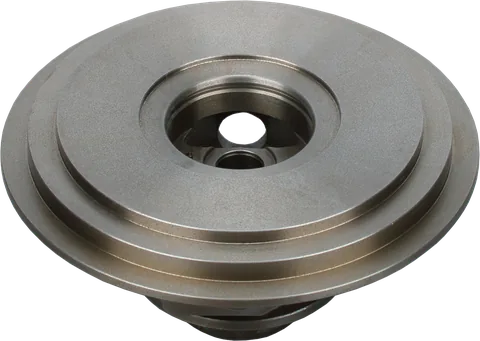
Product photograph from 2026. Numbers identify the features explained below.
3. Disassemble in controlled groups
Keep every spacer and retainer in sequence, even when replacements are planned. A photograph can reveal a reversed oil deflector later.
- Record orientation. Mark the clocking of both end housings against the center housing with removable marks on stationary surfaces. Record any permitted rotor indexing separately; never file or punch balance-critical parts.
- Remove the housings. Release retainers in the specified sequence. Support the cartridge and lift each housing squarely clear of its wheel. If corrosion prevents separation, stop before prying against blades or cocking the assembly.
- Release the compressor nut. Verify thread direction first. Hold only the designated shaft or wheel-hub feature, then loosen the nut with supported hand tools. Do not use an impact wrench or grip blade tips.
- Separate the rotating parts. Remove the nut and compressor wheel without levering on the backplate. Withdraw the turbine shaft when directed by the service procedure; resistance can indicate deposits or internal damage.
- Empty the center housing. Remove the backplate or seal insert, then the thrust collar, thrust bearing, deflectors, journal bearings, and retainers as applicable. Record faces, oil-hole orientation, and each spacer position.
4. How to clean turbocharger parts without changing geometry
Degrease housings with a cleaner compatible with their materials, followed by the specified rinse and drying process. A suitable ultrasonic cleaner can help remove deposits, but its chemistry must suit aluminum and other exposed materials.
Clean wheels gently with an approved solvent or detergent and a soft brush. Avoid blasting media, wire wheels, abrasive pads, and caustic cleaners on aluminum wheels. Do not sand blade edges or polish away contact damage.
Keep abrasives away from shaft journals, seal bores, and bearing passages. Blasting detached castings belongs in a controlled process with masking and thorough decontamination; residue can ruin fresh bearings. Flush oil galleries and verify that each passage is clear. Never spin the rotor with compressed air.
5. Measure to determine which turbocharger parts can be reused
Understanding how to rebuild a turbocharger means knowing when measurements rule out a kit repair. Inspect cleaned components under good light, then record dimensions against the applicable service limits.
| Inspection point | Pass cue | Fail or specialist-assessment cue |
|---|---|---|
| Shaft journals and runout | Diameters, roundness, and runout meet limits | Scoring, heat damage, undersize journals, or excessive runout |
| Wheels and hubs | Intact blades and sound hub surfaces | Cracks, bent blades, erosion, or rubbing marks |
| Bearing bores | Size, taper, and roundness meet limits | Enlarged, scored, or distorted bores |
| Thrust faces and collars | Undamaged working surfaces within limits | Grooves, heat distress, or worn locating surfaces |
| Ring grooves and seal bores | Clean seating surfaces and specified clearances | Chipped lands, widened grooves, scoring, or excessive clearance |
| Compressor and turbine housings | Sound contours, mounts, and accepted casting condition | Cracks, erosion, distortion, or contact damage outside acceptance criteria |
| Housing locating pilots | Correct diameter and roundness | Distortion that prevents correct alignment or sealing |
| Oil passages and drain cavity | Fully clear after cleaning | Persistent deposits, trapped debris, or damaged passages |
Measure journals and bores in multiple positions to reveal taper and ovality. Do not straighten a bent shaft, hand-grind a housing for clearance, or enlarge a bore to accept standard bearings. Any machining requires an approved repair specification and matching parts.
6. Match the kit, then assemble the cartridge
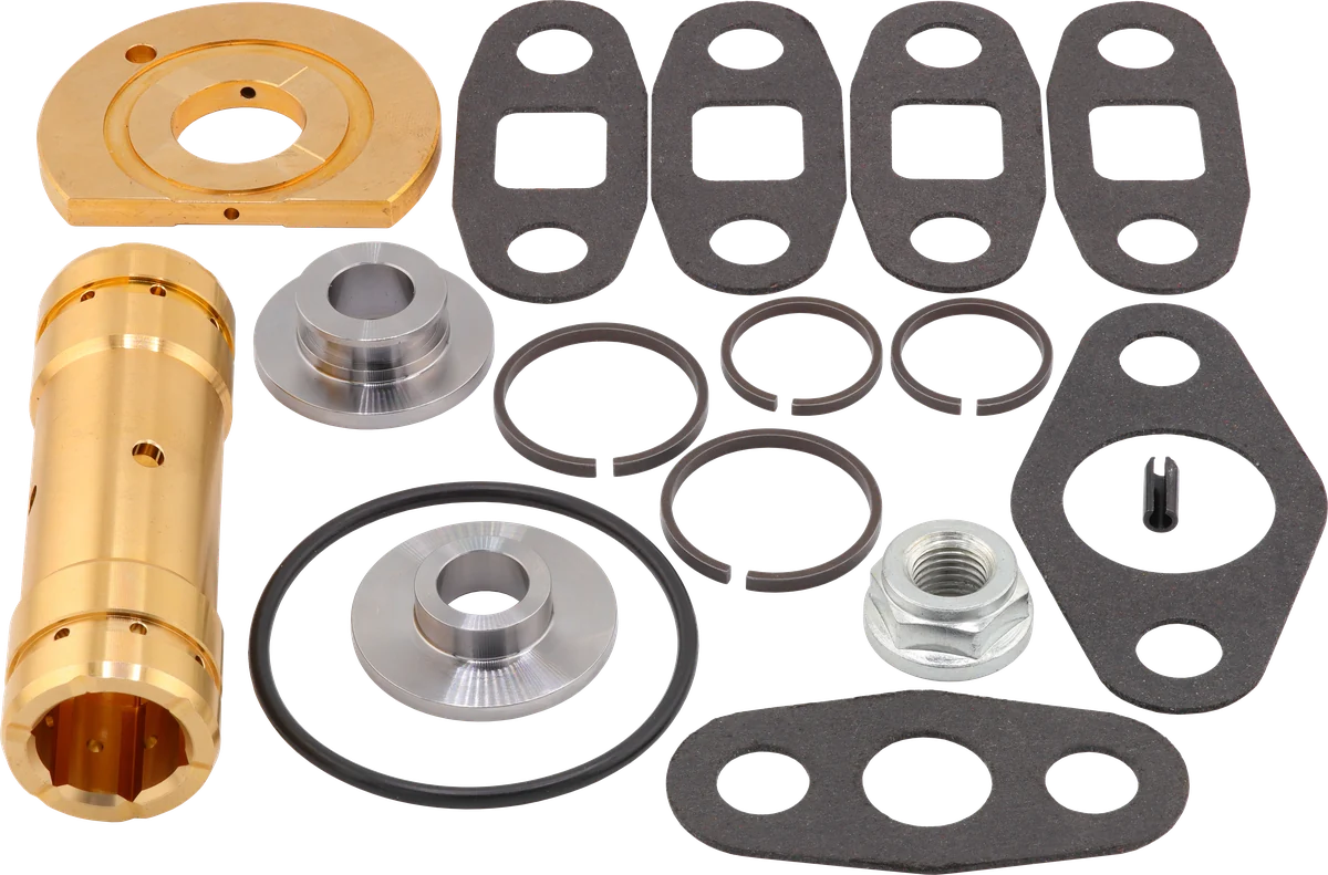
A turbo repair kit installation replaces service parts; it cannot restore worn castings or damaged wheels. Verify the kit by turbo part number and revision, not appearance alone.
| Potential kit contents | What to verify |
|---|---|
| Journal bearings | Size, style, and oil-feed arrangement |
| Thrust bearing and collar parts | Correct matched stack; contents vary |
| Metal sealing rings and elastomer seals | Correct sizes, profiles, and quantities |
| Retainers, fasteners, and shaft nut | Included only where specified; check replacement requirements |
Many kits exclude the backplate, heat shield, wheels, or shaft. Replace rejected components separately or recalculate the cost of a CHRA.
Lay out new parts beside the diagram. Extra pieces in a multi-application kit are not an instruction to install them all. Follow the specified lubrication state during assembly and clearance checks; use only the prescribed lubricant.
For a conventional serviceable cartridge, the assembly checkpoints are:
- Bearing installation: Install internal bearing stops, bearings, and outer retainers in the prescribed order. Confirm each retaining ring is fully seated and oil-control sleeves are present where required.
- Sealing rings: Check the specified ring clearances, including end gap and groove clearance where required. Expand rings only enough to enter their grooves. Do not twist, overstretch, or file them to fit without explicit instructions. Follow the specified gap orientation.
- Turbine shaft: Fit any heat shield in its designated position. Install the turbine-side ring and guide the shaft into place using the prescribed installation method. Unexpected resistance calls for withdrawal and inspection, not hammering.
- Thrust stack: Assemble collars, thrust bearing, spacers, and deflectors exactly as the diagram shows. Align oil feeds and install compressor-side sealing parts and the backplate without pinching seals.
- Compressor wheel and nut: Fit the wheel and specified nut. Apply the documented thread condition, tightening torque, and any additional angle. Support the holding tools to avoid bending the shaft.
There is no universal value for turbocharger compressor nut torque. Record the specified tightening sequence and apply a witness mark only if the service procedure calls for one. An old nut position does not establish correct tightening, and rotor indexing does not replace balancing.
7. Verify clearance and complete balancing
Measure axial end play with a dial indicator using the specified contact point and loading method. Measure radial movement at the designated location: movement at the wheel tip or nut is not automatically the bearing clearance.
Record results after final nut tightening. The rotor should turn smoothly by hand without scraping. If readings fail, investigate bearing selection, thrust-stack order, seating, and shaft condition before proceeding.
Turbocharger reassembly is incomplete until the required balance work is finished. Have a qualified shop perform component and assembled-cartridge balancing as specified for the unit, including high-speed verification where required. Agree with the shop who will perform final assembly and verification.
Reinstall accepted housings at the recorded clocking, tighten retainers to specification, and check for interference again. Complete any required actuator setup or calibration.
8. Prime the oil circuit and control the first start
Before installation, correct the failure cause and remove oil or fragments left in connected intake and exhaust components. An oil-filled charge-air system can feed an uncontrolled diesel overspeed; it must be cleared before starting.
Use new specified gaskets and seals. Confirm the oil supply is clean and the drain is unrestricted. Keep loose sealant and thread tape out of oil connections; use only the prescribed sealing method.
Introduce clean, engine-approved oil through the turbo inlet while turning the rotor gently by hand. Follow the engine manufacturer's prelubrication procedure, including any specified fuel-disabled cranking. Do not assume filling the turbo alone primes the engine's supply line.
With all ducting and guards restored, start and idle as instructed. Watch oil pressure and check for leaks, abnormal noise, or smoke. Shut down for missing oil pressure, scraping, or a major leak. Once checks pass, increase load progressively under the specified commissioning procedure and recheck connections.
Common Questions
Can a repair kit fix a smoking turbo?
Only if worn service parts caused the problem. Drain restrictions, crankcase pressure, damaged seal bores, and other engine faults need separate correction.
Can I rebuild a variable-geometry turbo with this procedure?
These steps cover the general cartridge workflow. Variable-geometry mechanisms and actuators need their own inspection, setup, and calibration procedures for the exact unit.
Are compressor nuts always left-hand thread?
No. Confirm thread direction from the service instructions for the turbo part number before loosening or tightening the nut.
Can I learn how to rebuild a turbocharger without balancing equipment?
You can learn inspection and assembly, but arrange the required balancing with a qualified turbo shop before starting. Alignment marks cannot verify balance.
Is replacing the CHRA easier than rebuilding it?
Usually, because a correctly supplied, balanced cartridge avoids internal rebuilding. Reusable housings, correct fitment, installation checks, and any required actuator calibration still matter.
Why is my turbocharger binding during reassembly?
Check bearing selection, thrust-stack order, seating, and shaft condition. The rotor should turn smoothly by hand without scraping; investigate failed clearance readings before proceeding.
Contact us at LeadTurbo with the turbo part number and engine details for help matching a repair kit, CHRA, or complete replacement turbocharger.