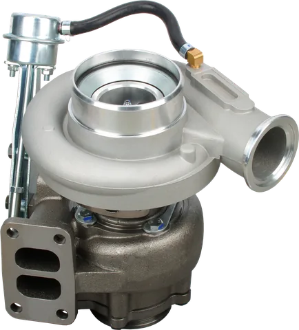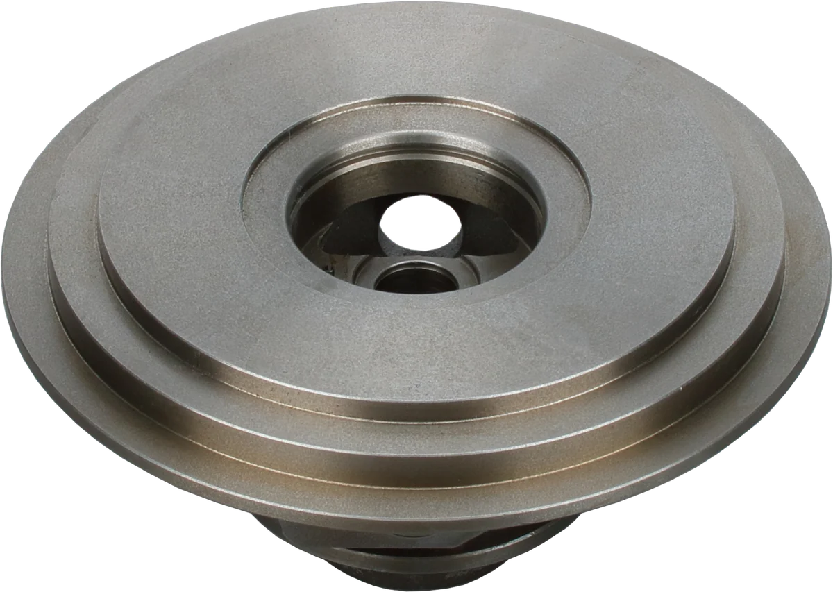
For a pickup, highway tractor, loader, or standby generator, installation includes checking the complete oil circuit. A new CHRA cannot compensate for a dirty supply pipe or a return that backs up. Start with the engine service procedure and instructions for the exact replacement assembly: mounting angles, passage sizes, fittings, and priming requirements depend on the application.
How should a turbo oil drain line be routed?
The engine pump delivers oil to the turbocharger under pressure, but that pressure drops as oil passes through the bearing system. Oil reaching the drain cavity leaves mainly by gravity. The drain generally needs a larger passage than the pressurized feed because returning oil can carry entrained air.
Use the specified internal diameter throughout the path, including flanges, elbows, adapters, and the engine entry. Keep the run short and continuously downhill, with enough flexibility to avoid a sharp bend or tension.
| Feature | Installation check | Why it matters |
|---|---|---|
| Internal diameter | Maintain the specified bore through every fitting. | A narrow adapter can limit the entire return. |
| Route | Maintain a continuous fall toward the engine. | An uphill section or sag can hold oil. |
| Length | Use the shortest practical approved path. | Extra length adds resistance and opportunities for low spots. |
| Engine return entry | Keep the entry above the specified operating oil level. | A submerged outlet adds resistance to drainage. |
| Heat clearance | Follow the approved routing and heat protection requirements. | Exhaust heat can damage hose and promote internal deposits. |
When checking turbocharger oil drain line routing, reject kinks, flattened sections, and low loops, even if the ends line up. Use oil-compatible hose rated for the local temperature, or the specified formed tube.
For equipment working on slopes or a marine installation, account for the approved operating attitude. A connection clear of oil on level ground may become submerged when the machine tilts. Do not relocate the return entry without an installation specification.
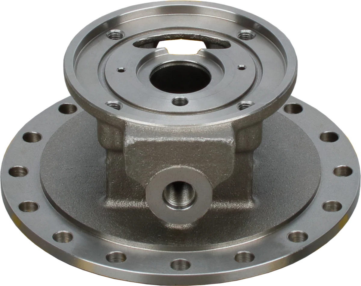
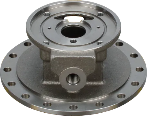
Central bore: houses the shaft and bearing system.
Mating surface: check cleanliness and damage.
Product photograph from 2026. Numbers identify the features explained below.
Set the bearing housing before connecting the pipes
Position the bearing housing, also called the center housing, before finalizing intake and exhaust connections. Its drain opening should be near the lowest point, within the manufacturer's permitted rotation from vertical. This rotational adjustment is often called clocking.
Check the shaft's allowed inclination separately; a downward-facing outlet alone does not establish correct mounting.
There is no universal diesel turbocharger oil drain angle. Use the drawing or installation instructions for the exact unit. Do not rotate the center housing merely to make a difficult return hose fit.
Where housing adjustment is permitted, follow the specified procedure and tightening sequence. Variable-geometry mechanisms, actuator brackets, and linkages can limit what may be moved. If the replacement arrives indexed differently from the original, resolve that mismatch before installation instead of forcing the oil pipes into position.
Build a clean, correctly metered oil supply
A turbo oil feed line must deliver clean oil through the correct fittings. Install a new, approved line with a replacement turbocharger whenever possible. An old pipe can hide hard deposits or debris despite looking sound outside. Blowing air through it proves only that a passage exists.
Keep new parts capped until assembly. Verify that the engine supply port is clean, and investigate contamination remaining from the previous failure. Use the specified engine oil and filter. If the previous unit suffered bearing damage, resolve any supply fault before the replacement runs.
| Supply component | What to verify |
|---|---|
| Feed pipe or hose | Correct bore, pressure and temperature rating, routing, and end fittings. |
| Banjo bolt or inlet adapter | Correct part and passage arrangement; matching threads do not guarantee correct flow. |
| Specified screen or filter | Inspect or replace according to the engine procedure; do not remove or drill it out. |
| Metering device | Confirm whether the assembly already contains one before considering an additional restriction. |
A turbocharger oil feed line restrictor is appropriate only when the engine or turbocharger specification calls for it. Bearing type alone does not establish the required orifice. An extra restriction can reduce lubrication, while removing required metering can create excessive supply. Never use a restrictor as a substitute for correcting a blocked return.
Why is my turbocharger drain backing up?
Gravity drainage depends on conditions at both ends of the return. Excessive crankcase pressure reduces the pressure difference available for oil to leave the bearing housing. A clear hose can therefore back up if crankcase ventilation is restricted or engine blow-by is excessive.
Before blaming the replacement turbo, check:
- The oil level, measured using the engine's specified method.
- Breather hoses, separators, and serviceable elements for blockage or damage.
- Crankcase pressure against the engine specification, under the required test conditions.
- Any history of rising oil level, heavy blow-by, or repeated oil leakage.
If ventilation service does not restore normal pressure, investigate the engine condition. A larger return hose will not correct an underlying crankcase-pressure fault. Keep the approved breather arrangement intact.
Keep gaskets aligned and oil passages clear
Clean both mating faces and remove old gasket material without dropping debris into open ports. Fit the correct new gasket, sealing washers, or O-rings, and check that each opening aligns with the passage.
Do not add silicone to a drain flange. Squeezed-out material can obstruct the return or enter the lubrication circuit. Use only the specified sealing method; any expressly required thread-sealing product must stay clear of the oil passage. Do not add tape or paste to flare, banjo, or O-ring joints.
Tighten to the specified torque with the pipe naturally aligned. Bolts should secure a seated flange, not pull a bent pipe into place.
How to install turbocharger oil lines: preparation through the first run
Work on a cool, secured engine and keep ports covered until their connections are ready.
-
Confirm the application. Match the turbo or CHRA, mounting arrangement, oil fittings, and installation instructions to the engine. Identify the previous failure cause before installing another assembly.
-
Prepare the engine. Correct contamination and ventilation faults. Check oil level and complete the specified oil and filter service. If the old turbo passed oil into the intake, remove accumulated oil using the engine service procedure before starting.
-
Set and secure the housing. Verify drain orientation and permitted shaft inclination. Check actuator clearance and retain required brackets and heat shields.
-
Fit the turbo oil drain line. Check the entire internal path for restrictions, including gasket edges and adapters. Establish a steady descent to the approved return connection.
-
Support the plumbing. Allow for engine movement without tension, rubbing, or a collapsing bend. Keep hoses away from exhaust surfaces and use specified heat protection.
-
Prepare the feed connection. Install the clean replacement supply line and specified screens or metering parts. Keep the inlet accessible for the required priming procedure.
-
Prime the turbocharger. Introduce the specified clean engine oil through the oil inlet as directed by the supplier. If instructed, turn the rotor gently by hand to distribute oil; never spin it with compressed air.
-
Complete the connections and prelubricate. Tighten fittings to specification. Follow the approved engine prelubrication procedure. Where it calls for cranking without firing, use the specified method to prevent starting and observe starter duty limits. Complete any required supply check at the turbo.
-
Make the first start at idle. Watch oil pressure and inspect accessible connections without approaching moving or hot parts. Stop promptly if pressure is abnormal or a significant leak appears.
-
Recheck after shutdown. Let the installation cool, inspect for seepage and contact marks, and verify oil level. Complete the specified operational check before returning the vehicle or machine to normal duty.
Symptoms that point toward a plumbing problem
These observations narrow the inspection; they do not prove that the turbocharger itself is sound or faulty. Check external leaks separately from oil entering the intake or exhaust.
| Symptom | Possible line or installation problem | First useful check |
|---|---|---|
| Oil around the return flange | Misaligned gasket, damaged seal, distorted flange, or pipe tension. | Inspect fit and sealing faces after shutdown. |
| Blue smoke soon after replacement | Restricted return, incorrect center-housing orientation, or excessive crankcase pressure. | Check drain routing and ventilation before changing feed metering. |
| Leakage mainly on slopes | Oil covering the return entry or a route losing its downhill fall. | Compare the installation with permitted operating attitudes. |
| New bearing noise or rapid distress | Blocked supply, wrong adapter, extra restrictor, or missed priming. | Stop running and verify the supply using the approved procedure. |
| Oil leaking at a feed fitting | Wrong sealing parts, damaged seat, or pipe strain. | Confirm fitting type, alignment, and torque specification. |
| Leakage or smoke returning after hose replacement | Heat-damaged hose, repeated sagging, or unresolved crankcase pressure. | Inspect support, shielding, and crankcase test results. |
Persistent smoke also has causes outside the oil plumbing. Do not assume all smoke means a failed seal, or continue running when oil accumulation or bearing damage is suspected.
Common Questions
How much can I rotate the center housing?
Use the installation limit for the exact turbocharger. The outlet should sit near the bottom of the housing, within the allowed deviation from vertical. Clocking limits and shaft inclination limits are separate checks.
Should I install a restrictor to stop oil smoke?
Only install the metering device specified for that engine and turbocharger. Smoke can result from a restricted return, high crankcase pressure, or other faults. Reducing the supply without specifications can damage the bearings.
Can I make a turbo oil drain line smaller to fit?
Do not reduce the specified internal passage size to clear an obstruction. Reroute the line or use the approved fitting arrangement. A narrow adapter can become the limiting passage even when the hose itself looks large.
Does a new CHRA arrive ready for a dry start?
Do not assume assembly lubricant replaces installation priming. Add the specified clean oil at the inlet and complete the engine manufacturer's prelubrication procedure before starting. Use the supplied installation instructions for the exact assembly.
Can I use silicone on the drain flange?
Do not add silicone to the drain flange. Install the specified gasket or O-ring on clean, undamaged surfaces, with the opening aligned. If the flange leaks, correct its condition or fit instead of adding sealant.
Should I replace the turbocharger feed line?
Install a new, approved line with a replacement turbocharger whenever possible.
Turbocharger oil feed vs drain: what's different?
The feed delivers oil under pressure; the drain works mainly by gravity and generally needs a larger passage.
For help matching a replacement turbocharger, CHRA, or installation parts, contact LeadTurbo with the turbo part number, engine model, and equipment details.