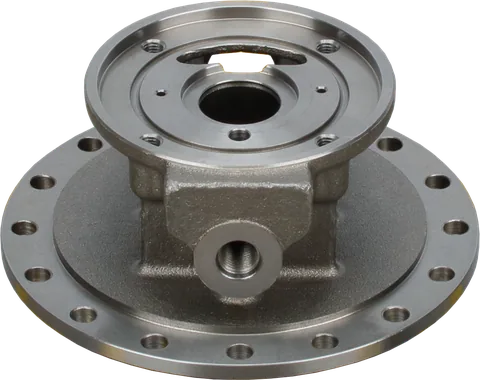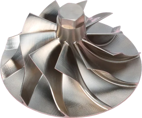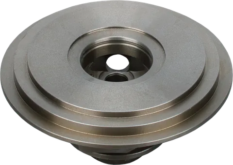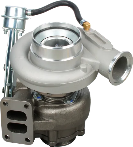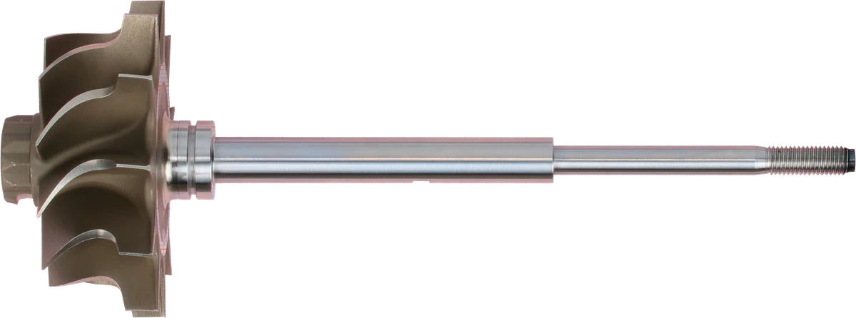
For rebuilders working on truck, construction, agricultural, marine or generator turbos, the turbo shaft nut deserves the same attention as the rotating components it secures. Its size gives little indication of its importance. A wheel can appear fully seated while the joint has too little preload, damaged threads or an incorrect tightening condition.
What does compressor nut torque actually control?
Tightening the nut places the shaft in tension and compresses the wheel and its specified supporting stack. That preload holds the mating faces together.
In a conventional friction-clamped assembly, friction between those loaded faces transfers driving torque from the turbine shaft to the compressor wheel. The wheel bore establishes radial location; a close bore fit alone does not provide the required axial clamping force.
Preload also helps keep the wheel seated consistently. If the joint slips or settles, the wheel's position or angular relationship to the shaft can change. A previously balanced assembly can then develop vibration.
Clamping does not create balance by itself. It preserves the mechanical relationship that a correctly assembled and balanced rotor depends on.
The joint must retain adequate clamp load during operation, when temperature differences and centrifugal deformation can change the dimensions of the wheel and shaft. That requirement is built into the specified assembly procedure.
Understand through-bore and boreless attachments
“Bore fit” describes the relationship between mating diameters. “Through-bore” and “boreless” describe different wheel attachment arrangements. They are not interchangeable descriptions.
On a common through-bore wheel, the shaft passes through the hub. The front nut compresses the wheel against the specified rear abutment and associated components. Those parts must seat correctly for tightening to produce the intended preload.
| Arrangement | How the wheel is located or attached | Service implication |
|---|---|---|
| Through-bore with a close sliding fit | The bore locates the wheel around the shaft; the nut clamps the assembly | Easy sliding assembly does not mean the joint can operate with reduced preload |
| Through-bore with a specified interference fit | The fit provides additional restraint and may contribute to the connection | Follow the prescribed installation process and nut procedure; do not force a cold wheel into place |
| Boreless wheel | No shaft hole passes completely through the hub; attachment may use a blind threaded connection or another engineered interface | A conventional front retaining nut may be absent, so through-bore instructions may not apply |
Never enlarge a bore, polish down a shaft or heat a wheel simply to make assembly easier. An unexpected fit can indicate mismatched parts, contamination, burrs or damage. Resolve the cause before tightening.
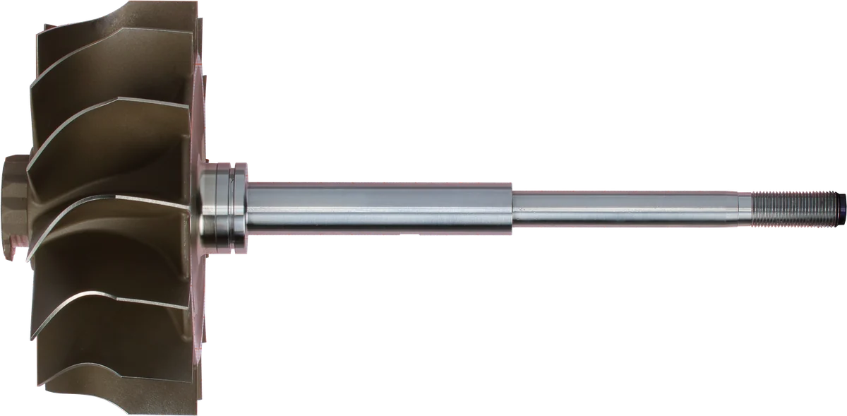
Turbine wheel: exhaust energy drives the shaft.
Shaft surface: inspect wear and scoring before reuse.
Shaft end: connects to the compressor-side rotating parts.
Product photograph from 2026. Numbers identify the features explained below.
Why thread roots and shaft steps are vulnerable
The threaded end carries the tensile load created during tightening, but its smallest load-bearing section is at the thread roots. Those roots also act as geometric notches, concentrating stress locally. Load is not distributed equally across every engaged thread.
A shaft shoulder presents another change in section. Its transition radius helps control stress concentration, but scratches, corrosion pits or damage at that transition can become fatigue starting points.
These areas experience more than assembly tension. Bending from imbalance, rubbing or other operating loads adds stress. Repeated loading can grow a crack even when the shaft has never visibly bent or suffered an obvious overload.
Controlled turbo shaft stretch is part of developing preload. Excessive permanent elongation or local necking is different: it indicates damage unless the assembly explicitly uses a validated yielding procedure.
During inspection:
- Examine thread roots, the first engaged threads and shoulder transitions.
- Reject cracked, necked or otherwise out-of-specification shafts.
- Do not reshape shoulder radii or dress thread roots to conceal damage.
- Follow the repair procedure's inspection and reuse limits.
A nut that turns onto damaged threads is not proof of a serviceable shaft.
Confirm thread direction before applying force
Turbochargers can use right-hand or left-hand compressor-end threads. Viewed directly at the compressor-end nut, a right-hand thread loosens counterclockwise; a left-hand thread loosens clockwise.
Thread hand may be selected so operating reaction torque tends to resist loosening. That feature does not replace proper preload, and it does not guarantee that an incorrectly assembled nut will remain secure.
Confirm turbocharger nut thread direction using the exact assembly identification, service information and replacement hardware before turning the wrench. Engine model alone may not identify the rotor arrangement.
If the nut resists unexpectedly, stop. More force in the wrong direction can overload the shaft or damage the holding feature. For tightening, use a torque wrench suitable and calibrated for the required direction.
How to tighten a turbocharger nut: methods compared
A diesel turbocharger compressor nut torque specification is valid only with its stated hardware, thread condition and tightening sequence. Do not substitute a different method because the necessary tool is unavailable.
The objective is controlled preload. Each method approaches that objective differently.
| Method | What controls the final tightening | Advantages | Limitations and requirements |
|---|---|---|---|
| Torque only | Applied turning resistance | Practical, familiar and straightforward to document | Friction strongly affects the resulting preload; requires the specified lubricant condition and suitable tool accuracy |
| Torque plus angle | An initial seating stage followed by a specified rotation | Can reduce preload variation caused by friction after seating | Depends on correct seating, joint geometry and an accurate starting point; requires the exact prescribed sequence |
| Measured shaft stretch | Elongation between defined reference points | Measures a response more directly related to shaft tension | Requires a validated stretch target, suitable access, precise measurement and controlled measurement conditions |
Torque plus angle does not automatically mean the shaft is tightened into yield. That depends on the design and procedure.
Stretch measurement also requires interpretation. Measuring between the wrong points, starting from an incorrect baseline or allowing temperature changes to affect the reading can produce misleading results.
Use the OEM or approved repair kit specification for every tightening stage. Follow any specified seating or release steps exactly; do not invent extra cycles to make the readings seem more consistent.
Dry vs lubricated turbocharger threads: preload differences
A torque wrench measures turning resistance, not clamp load. Much of that resistance comes from friction in the threads and beneath the nut's bearing face.
Lubrication generally reduces friction. Applying the same torque to lubricated threads can therefore create more shaft tension than applying it to dry threads. Changing the lubricant can also change the result.
The required condition includes both the threads and the nut seating face. “Lightly oiled” and “dry” are assembly instructions, not optional preferences.
- Use only the specified lubricant and application method.
- Keep mating faces clean and prepared as directed.
- Do not add anti-seize or threadlocker unless expressly required.
- Do not use a generic torque correction to compensate for an unknown surface condition.
Unexpectedly high resistance may indicate damaged threads or poor seating. Reaching the wrench setting does not prove adequate preload.
Counter-hold the designated hex and support the rotor
Use the shaft or turbine-end hex identified by the service procedure, together with the specified holding fixture. If the rotor requires a dedicated tool, use it.
Never counter-hold through the compressor or turbine blades. Blades are not wrenching surfaces. Gripping them, wedging them against a housing or using a screwdriver between them can damage the wheel and impose bending loads.
Support the assembly so the socket and holding tool remain aligned. Avoid pulling sideways on an unsupported shaft or allowing the fixture to rock as the nut turns. Do not clamp bearing journals or use an impact wrench.
Before disassembly, record any existing wheel-to-shaft balance index marks. Where reference marking is permitted, use a method and location that will not damage a stressed surface. Do not punch or scribe thread roots, shoulder transitions or blades.
Preserving an index helps retain a known component relationship. A replacement nut and any disturbed seating still require the balance verification specified for the completed rotor.
Recognize over-tightening and under-tightening damage
A nut can feel secure while the assembly is mechanically wrong. Both insufficient preload and excessive tightening can lead to a broken shaft, although the damage develops differently.
| Assembly problem | What can happen | Evidence worth investigating |
|---|---|---|
| Insufficient preload | Faces slip, fret or settle; the wheel can loosen or shift | Fretting debris, polished contact patches, changed index position or wheel contact |
| Excessive tightening | Shaft elongation exceeds its allowance; necking, thread damage or hub damage can occur | Permanent dimensional change, distorted threads or cracking |
| Bending during tightening | Shaft runout or uneven seating compromises the rotor | Abnormal runout, rubbing or unexplained imbalance |
| Damaged threads or shoulder transition | Local stress concentration promotes fatigue cracking | Cracks originating near thread roots, notches or section changes |
Do not compensate for a suspect joint by tightening harder. Remove it from service and establish whether the shaft, wheel, nut or seating stack is damaged or incorrect.
Always replace the compressor wheel retaining nut whenever it is removed. Use the specified part, including its thread hand, bearing-face geometry and any locking feature.
Rotor assembly checklist
Before releasing a rebuilt diesel turbocharger, confirm these points against its service procedure:
- Identify the exact turbo assembly and matched shaft, wheel and nut.
- Obtain the complete OEM or approved repair kit tightening instructions.
- Verify thread hand before loosening or tightening.
- Inspect threads, shoulder transitions, wheel bore and contact faces.
- Confirm the specified fit and complete seating of every stack component.
- Install a new retaining nut.
- Prepare threads and seating faces to the specified dry or lubricated condition.
- Counter-hold the designated hex with the correct fixture.
- Keep wrench forces aligned and support the rotor against bending.
- Apply the specified torque, angle or stretch method without extra tightening.
- Preserve approved index references and complete required balance verification.
- Check free rotation, runout, clearances and end play as specified.
- Record the parts used, tightening method and inspection results.
If instructions are incomplete or components do not match, resolve that discrepancy before assembly proceeds.
Parts for this guide
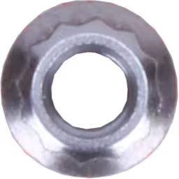 3597180 NU HX35W Turbocharger Shaft Nut Replacement
FOR 3597180 NU
Shaft Nut
In Stock
 319026 S200 Compressor Wheel for DEUTZ BF6M1013FC Turbocharger
319026
Compressor wheel
In Stock
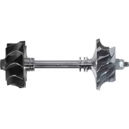 318704 RA Rotor Assy OM460LA Turbocharger Replacement
FOR 318704 RA
Rotor Assy
On backorder — orders accepted
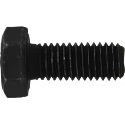 2840364 HX35W Turbocharger Shaft Nut for Komatsu PC200 Cummins 6BTAA
2840364
Shaft Nut
In Stock
Common Questions
Where do I find compressor nut torque for my turbo?
Use the service data for the exact turbocharger assembly or the instructions supplied with its approved repair kit. Match the shaft, wheel and nut part numbers. If the instructions omit thread condition, tightening sequence or thread hand, resolve those details before assembly.
Can I reuse a turbocharger nut?
No. Always install a new compressor wheel retaining nut of the specified part number. Reuse can change friction or locking behavior, and visual inspection cannot establish that the nut will produce the intended clamp load.
Does a close-fitting wheel bore prevent loosening?
No. In a conventional friction-clamped rotor, the bore locates the wheel while preload holds the driving faces together. A close fit cannot compensate for inadequate clamping. A specified interference fit requires its own assembly procedure.
How do I identify a left-hand thread?
Check the service information and the actual replacement hardware. Viewed at the compressor end, a left-hand nut loosens clockwise. Do not establish thread direction by forcing the nut or by assuming every turbo in an engine family uses the same arrangement.
Is measured shaft stretch always the best method?
Only when the assembly has a validated stretch specification and suitable measuring points. Stretch can improve preload control, but an improvised measurement or a target borrowed from another shaft is unreliable. Use the method specified for the exact assembly.
Do balance marks eliminate the need for balancing?
No. Index marks help preserve a known relationship between reused components, but they do not prove balance after assembly. Replacement parts, a new nut or changed seating can alter the result. Complete the balance verification required by the rebuild procedure.
Why does a turbocharger nut loosen?
Insufficient preload, damaged threads or incorrect tightening conditions can prevent the joint from remaining secure.
Which replacement turbocharger nut do I need?
Use a new compressor nut of the specified part number, matching thread hand, bearing-face geometry and any locking feature.
For help identifying replacement turbochargers, CHRAs, repair kits or turbo parts, contact LeadTurbo with your turbo part number and engine details.